UTP copper, multimode optical-fiber evolving at the speed of life
In the past ten years, the cabling industry has played a critical role in the rapid growth of technology. The constant need for more bandwidth fueled by high-end applications, the Internet, and e-mail—the communication method of choice—renders cabling infrastructure the most important constituent of continued technological progression.
Product development and processing capabilities, aimed at meeting higher transmission standards, spawned an evolution in UTP copper and optical-fiber cabling performance and technology. "We've come incredibly far in this aggressive, dynamic, and accepting community," says Val Rybinski, engineering services manager with Hitachi Cable Manchester (www.hcm.hitachi.com). "And that stems from this industry's creative ideas, great leaders, and ability to work together."
The way we were
Ten years ago, the onset of structured cabling triggered the development of standards and the introduction of publications like Cabling Installation & Maintenance. "It was a huge turning point—the first time that cabling became structured, and every workstation had the exact same interface," says Rybinski. "It amazed me that structure and interface was the same throughout the world. No other service to the end user was like that."
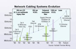
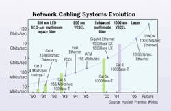
In 1993, Category 5 UTP copper cabling preformed at a frequency of 100 MHz and supported 10/100Base-T systems. Optical-fiber had gained a strong foothold with campus and premise backbone cabling. "At that time, cable and connectivity manufacturers began forming partnerships to offer end-to-end solutions and reduce the fears about which products were best," says Bill Slater, marketing manager for enterprise product, Leviton Voice and Data Division (www.levitonvoicedata.com).
null
The industry standard for backbone fiber was the fiber distributed data interface (FDDI)-grade 62.5/125-µm multimode fiber with LED-based transmitters operating at 850 nm, which most believed offered unlimited bandwidth for premise networks. Japan and central Europe had adopted 50-µm fiber as their standard. "Fiber choice was more application driven in the U.S., while countries like Japan tended to be driven more by performance and technology," says Tony Beam, director of business development for Tyco Electronics/AMP Netconnect (www.ampnetconnect.com). "IBM adopted some applications for 62.5, which then spilled over into FDDI, and set the stage for the cabling to go the same route."
With 62.5-µm fiber came easier installation and better coupling efficiency. "When multimode fiber made its way into the premise market, we wanted to offer a cabled fiber that was more craft-friendly—many who would be installing it didn't have a high level of optical-fiber handling expertise," says Doug Coleman, manager of technology and standards for private networks, Corning Cable Systems (www.corning.com). "62.5-µm fiber's bigger core and numerical aperture also allowed for better power coupling efficiency with the data transmission sources."
Between 1993 and 1997, a continued demand for more bandwidth increased data rates from 10 to 100 Mbits/sec. "The need for higher data speeds was driven by companies shifting from standalone PCs to more centralized servers and infrastructures," says Beam. In the late '90s, it became apparent that to support next-generation, high-bit-rate applications, cabling systems needed to run Gigabit Ethernet (GbE).
Copper cabling enhanced
In specifying GbE for UTP copper cabling, the Institute of Electrical and Electronics Engineers (IEEE; www.ieee.org) aimed to run it over the cable most installed—Category 5. "Because GigE utilizes bi-directional and full four-pair transmission, there's increased noise between pairs. This created new issues with crosstalk," explains Asef Baddar, application engineer for General Cable (www.generalcable.com). Running GbE over copper cabling at a frequency of up to 100 MHz brought about the Category 5e standard, which specified new requirements for parameters like power-sum near-end crosstalk (PSNEXT), return loss, and power-sum equal-level far-end crosstalk (PSELFEXT) for cable and connecting hardware.
Many well-installed Category 5 systems met new 5e standards. According to Baddar, poor installation attributed to about 80% of the reasons for not meeting 5e standards. "If a Category 5 installation was done poorly with stretched cables and pairs untwisted too much during termination, there was a pretty good chance it didn't meet 5e."
Connecting hardware and patch cords have played a large part in the evolution of UTP copper cabling systems. The challenge of going to 100 MHz and higher is compounded by the 'RJ' wiring scheme. "Analog telephone systems, or POTS, originally used the center two conductors of a jack. A second line was provided by placing conductors on each side of the center pair," explains John Siemon, vice president of global operations, The Siemon Company (www.siemon.com). "Because this configuration inherently increases crosstalk, thousands of R&D dollars have been spent coming up with today's high performance connector and patch cord designs."
One step further
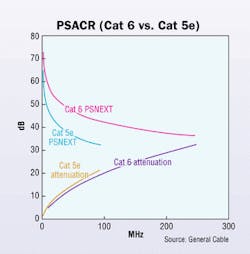
Even as TIA/EIA published the Category 5e standard, work was underway on a Category 6 standard, characterized to a 250 MHz frequency for supporting more data traffic and faster throughput for GbE. The Category 6 standard specifies positive attenuation-to-crosstalk ratio (ACR) to 200 MHz, and includes requirements for backward compatibility and interoperability. This created several new challenges for copper cable and connectivity manufacturers.
When UTP copper cables carry signals at higher frequencies, each active pair is more likely to affect the surrounding pairs. Meeting the stringent Category 6 requirements required new processes and designs. "The processing equipment used to manufacture Cat 6 cable gives us more consistent and tighter twists, which allows for more noise cancellation," says General Cable's Baddar. Cable manufacturers increased the cable's copper size to achieve a better signal power (ACR), and added a separator to reach specified NEXT values. "The separator is a pair-isolating center member often referred to as a spline," explains Baddar. The spline is a cross-web, tape, or filler that separates the four pairs from one another to further reduce crosstalk.
Redesigning connecting hardware to meet Category 6 requirements proved to be a more difficult endeavor, requiring new designs and technology to optimize crosstalk reduction. "The plug contributes crosstalk, and anything that terminates an eight-position plug must compensate for that imbalance by canceling out the crosstalk," explains Hitachi's Rybinski. "At 100 MHz, there was more tolerance of noise and we didn't need to be as precise correcting crosstalk. To tolerate 200 MHz, we needed much better compensation."
Since retooling and redesigning connectors from the ground up is difficult and expensive, initial attempts to achieve Category 6 performance relied on adding more compensation to existing Category 5e designs. According to Siemon, compensation has its limitations because it is frequency-dependent. "While correcting crosstalk may improve performance at 100 MHz, phase shifts can cause it to detract from performance at higher frequencies," says Siemon. "The more compensation used, the more difficult to achieve high performance over a broad range of frequencies."
According to Mike O'Connor, technical director for Hubbell Premise Wiring (www.hubbell-premise.com), achieving Category 6 backward compatibility and interoperability was also a difficult task. "Performance requirements are much more stringent. For example, the NEXT value for a Category 5e connector is 43 dB at 100 MHz, and the NEXT value for a Category 6 connector is 54 dB at the same frequency, which is a big step in noise reduction," says O'Connor. "Backward compatibility was solved fairly easily, but interoperability was trickier. Third-party testing is key to ensuring true Category 6 performance."
null
Many consider achieving Category 6 standards the biggest milestone for UTP copper cabling systems. "These products have a long history of different levels of performance. Achieving Category 6 performance while being backward compatible and interoperable is an enormous accomplishment," says Siemon. "It took collaboration and thousands of hours by many engineers from many different manufacturers."
Fiber gets a second look
Before GbE, 62.5-µm fiber was de facto for backbone and riser cabling, and in some cases, to the desktop. But as backbone speeds increased to GigE, 62.5-µm fiber came under scrutiny. The light-emitting diode (LED) signaling technology, which for years had been the low-cost, preferred transmission source, was no longer a viable solution. "LEDs could only be turned off and on a certain number of times per second, and were limited to approximately 622 Mbits/sec," explains Coleman. "That forced the industry to move to laser technology." Vertical-cavity surface emitting lasers (VCSELS), already in development and deployed for data centers, became the transmission source of choice for running GbE.
While 62.5 and 50-µm fiber provide similar performance with VCSELS at a 1300 nm wavelength, VCSELS were developed and deployed for the 850 nm operating window. "One of the biggest questions was whether 850 nm or 1300 nm would be the winning wavelength for high speed data," says Beam. "850 nm ended up being the better solution for VCSELS because it was simpler, more reliable, and cost-effective."
Laser-based data transmission over multimode fiber produces an effect called differential mode delay (DMD), which happens when a laser beam in launched into the center of a fiber's core, and the beam splits into several modes of light. "With DMD, the modes of light reach the receiver at different times, causing signal distortion and reduced transmission capacity," explains Mauricio Silva, director of technology for General Cable. "A smaller fiber core has fewer modes of light excited and less distortion." Because 50-µm fiber has a smaller core, it can transmit light for longer distances than the larger-cored 62.5-µm fiber.
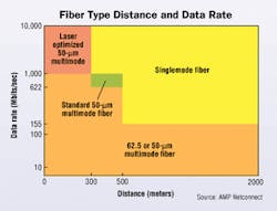
In specifying multimode fiber, the goal was to support distances up to 500 meters for campus backbone infrastructures. For GbE, 62.5-µm fiber channel length is limited to 220 meters, which caused 50-µm fiber to be included in TIA/EIA-568-B.3 for structured cabling and connectivity standards. "Switching to VCSELS to run GigE was not so much a problem for 62.5-µm fiber as it related to inside smaller premise networks and shorter runs," says Beam. "But with distances greater than 300 meters, and the knowledge that speeds wouldn't stop at 1 Gig, the industry needed to include 50-µm fiber." According to Beam, it was a tough transition: "Based on the evidence we had, and the best ability to look forward, for decades we had promoted, sold, and positioned 62.5-µm fiber as the cabling you would never have to replace."
To avoid defects present in some multimode fiber, manufacturers developed offset-launch patch cords that launch the light source several microns from the center of the core. Offset-launch patch cords are required in the IEEE 802.3z standard for 1300 nm wavelengths. "Launching the light about 20 µm from the center of the core allows it to go around centerline dips and reduce dispersion," explains General Cable's Silva.
According to Martyn Easton, product line manager of flame-retardant cables for Corning Cable Systems, the migration from a fiber that was easier to install to fiber with better transmission performance was made possible in part by the evolution of fiber connectivity performance and technology. "Many companies worked diligently to make field terminations easier and quicker by developing connectors with a push-pull functionality," says Easton. "These advancements superceded the need to use 50-µm fiber for longer distances, so connectivity does not have as much of an effect on performance of fiber cabling systems as it does with copper."
The ST connector (straight tip) was considered the standard connector until the industry developed the SC, with its push-pull mating design. The SC became the recommended connector for structured cabling under the TIA/EIA-568-B standard, with the ST grandfathered in. "It took a long time for SC connectors to win over the marketplace," says Beam. "There's still a base of customers using the ST, and for that reason, it lives on."
While the original battles over optical-fiber connectors focused more on functionality and usability, recent developments are based more on cost. Small-form-factor connectors offer higher port density, with a smaller footprint and featuring "a single ferrule design where two fibers are embedded within one ferrule," explains Easton. "This enables more ports per switch and lower cost per port."
Where do we go from here?
IEEE recently formed a 10GBase-T study group to investigate delivering 10-GbE over UTP copper, and many are anxiously awaiting the results. "Most believe that Category 6 should be the choice when it comes to running 10 Gig over copper," says Baddar. "As manufacturers, we're trying to demonstrate to IEEE that Cat 6 is the better choice, because while today it may only total 20% of the installations, by 2005, that figure will increase to 70% or 80%."
Category 6 has characterized channel performance to 250 MHz, and as we move towards higher data speeds, there will be a need to characterize UTP copper cabling to higher frequencies. "There will be efforts to understand the range and performance characteristics for systems to 500 MHz," says Siemon. "Specifying requirements that control balance and immunity to external noise will be key to extending the throughput of copper cabling beyond 1 Gig per second."
According to Hubbell's O'Connor, the industry will continually work to improve product, but it will be a challenge to run 10-GbE over copper. Nevertheless, he says, "A Category 6 cabling infrastructure specified to 250 MHz is much more capable of supporting 10 Gig than one only specified to 100 MHz, like Category 5e."
Today, 62.5-µm fiber cabling provides suitable data rates for many customers; however, as the industry moves towards 10-GbE in the backbone, the use of 50-µm fiber will increase. "I really do not see 62.5 playing in the 10 Gig arena," says Beam. "At those speeds, it has a distance limitation of about 60 meters, and for all practical purposes, is a non-solution."
Laser-optimized 50-µm fiber, with alterations to the index of refraction profile, has demonstrated 10-GbE performance to 300 meters, without the need for offset-launch patch cords or changes to connectors and installation methods. "To create laser-optimized 50-µm fiber, we've given it sort of an engine upgrade," explains Corning's Easton. He says no active equipment is available to run 10-GbE, but the bandwidth scalability of 50-µm fiber provides the ultimate media solution to support legacy and future application needs.
As the demand for bandwidth grows, 40 and 100-GbE may become a reality sooner than we think, and some doubt the ability of multimode fiber to support those data rates. "If we ever get to 40 or 100 Gig, we may see a migration from multimode to singlemode in the backbone," says Silva. "If laser technology becomes cost-effective, it's possible that somewhere down the road, singlemode may be the fiber of choice."
With several optical-fiber connectors available, many are aware of the need for a standard interface as the industry moves forward. "Several factors go into deciding what type of connector to use, including personal preference of the person writing the specification," says Harley Lang, product manager for fiber products, Leviton. "I think eventually, the market will decide on a connector."
A subsiding battle
UTP copper and optical-fiber cabling coexist, with fiber de facto in the backbone. But with data rates of 10 or even 100-GbE, there is some speculation regarding the capacity for copper cabling. "There's definitely still a battle between copper and fiber, but the intensity of that battle has decreased tremendously over the past ten years," comments Beam. "Ten years ago, some thought FDDI would cause the death of copper. Then we thought Gigabit Ethernet would cause the death of copper. So, I don't necessarily believe that 10 Gig will be the death of copper."
According to Beam, zone cabling, with fiber into the horizontal and short runs of copper to the desktop, will maintain the coexistence of UTP copper and fiber cabling. "Many companies have a huge investment in their PCs and laptops, which are all outfitted with a copper interface," says Beam. "The idea of fiber-to-the-zone allows that copper interface to live on."
According to Siemon, "Copper provides an infrastructure able to support both 30-year old applications, including analog telephone service, and those not yet available." Although copper systems appear to be keeping pace with networking technologies, there's a strong future for increased penetration of fiber into the horizontal.
"The answer," says Siemon, "is not one or the other, but both."
Betsy Ziobron is a freelance writer covering the cabling industry.


