Advantages of using higher-quality shielded cabling to power remote network devices

From the April, 2014 Issue of Cabling Installation & Maintenance Magazine
Heat buildup and contact arcing can cause component damage in systems with lower-quality cabling systems ill-equipped to handle these conditions.
By Valerie Maguire, Siemon
Remote powering applications utilize the copper balanced twisted-pair information technology (IT) cabling infrastructure to deliver DC power to Internet Protocol (IP)-enabled devices. The popularity of this technology and the interest in expanding its capabilities is staggering. Consider the following.
- More than 100 million Power over Ethernet (PoE)-enabled ports are shipping annually.
- Cisco 60-watt (60W) Universal PoE (UPOE) technology is driving the adoption of virtual desktop infrastructure (VDI). When paired with Cisco's EnergyWise IOS-based intelligent energy management solution, the technology supports using the IT network to monitor and control power consumption, as well as turn devices on and off remotely to save power when the devices are not being used.
- Published, but not yet commercially available, Power over HDBase-T (POH) technology can deliver up to 100W over twisted-pair cable to support full high-definition (HD) digital video, audio, 100Base-T and control signals in TV and display applications.
- The IEEE 802.3bt DTE Power via MDI over 4-Pair Task Force is developing a new remote powering application that will provide superior energy efficiency compared to a two-pair application and significantly expand the market for PoE systems.
In less than a decade, remote powering technology has revolutionized the look and feel of the IT world. Now, devices such as surveillance cameras, wireless access points, radio frequency identification (RFID) readers, digital displays, IP phones and other equipment all share network bandwidth that was once exclusively allocated for computers.
It is common knowledge that the networking of remotely powered devices for autonomous data transmission and collection is driving the need for larger data center infrastructures and storage networks. However, many IT managers are not aware that remote power delivery produces temperature rise in cable bundles and electrical arcing damage to connector contacts. Heat rise within bundles has the potential to cause higher bit errors because insertion loss is directly proportionate to temperature. In extreme environments, temperature rise and contact arcing can cause irreversible damage to cable and connectors. Fortunately, the proper selection of network cabling can completely eliminate these risks.
Choosing higher-quality and specially qualified shielded Category 6A and Category 7A cabling systems provides the following advantages to ensure a "futureproof" cabling infrastructure capable of supporting remote powering technology for a wide range of topologies and operating environments.
- Assurance that critical connecting hardware contact mating surfaces are not damaged when plugs and jacks are cycled under remote powering current loads.
- Higher maximum operating temperature for IEEE 802.3 Type 2 PoE Plus applications.
- Fully compliant transmission performance for a wider range of channel configurations in environments having an ambient temperature greater than 20 degrees Celsius (68 degrees Fahrenheit).
- An option to support remote powering currents up to 600mA applied to all four pairs and all networking applications up to and including 10GBase-T in 70-degree-Celsius (158-degree-Fahrenheit) environments over a full four-connector, 100-meter channel topology.
- Reliable and thermally stable patching solutions for converged zone cabling connections (e.g. device to horizontal connection point) in hot environments.
Protecting your connections
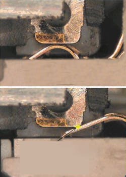
Telecommunications modular plug and jack contacts are carefully engineered and plated (typically with gold or palladium) to ensure a reliable, low-resistance mating surface. Today's remote powering applications offer some protection to these critical connection points by ensuring that DC power is not applied over the structured cabling plant until a remotely powered device (PD) is sensed by the power sourcing equipment (PSE). Unfortunately, unless the PD is shut off beforehand, the PSE will not discontinue power delivery if the modular plug-jack connection is disengaged. This condition, commonly referred to as unmating under load, produces an arc as the applied current transitions from flowing through conductive metal to air before becoming an open circuit. While the current level associated with this arc poses no risk to humans, arcing creates an electrical breakdown of gases in the surrounding environment that results in corrosion and pitting damage on the plated contact surface at the arcing location.
While it is important to remember that arcing and subsequent contact surface damage is unavoidable under certain mating and unmating conditions, contacts can be designed in such a way as to ensure that arcing will occur in the initial contact "wipe" area and not affect mating integrity in the final seated contact positions. The photos depict an example of such a design that features a distinct "make-first, break-last" zone that is separated by at least 2 millimeters from the fully mated contact zone on both the plug and outlet contacts. Note that any potential damage due to arcing will occur well away from the final contact mating position for this design.
To ensure reliable performance and contact integrity, it is recommended that only connecting hardware independently certified for compliance to IEC 60512-99-001 be used to support remote powering applications. This standard was specifically developed to ensure reliable connections for remote powering applications deployed over balanced twisted-pair cabling. It specifies the maximum allowable resistance change that mated connections can exhibit after being subjected to 100 insertion and removal cycles under a load condition of 55V DC and 600mA applied to each of the eight separate plug/outlet connections.
Keeping it cool
The standard ISO/IEC operating environment for structured cabling is -20 degrees Celsius to +60 degrees Celsius (-4 degrees Fahrenheit to +140 degrees Fahrenheit). Compliance with industry standards ensures reliable long-term mechanical and electrical operation of cables and connectors in environments within these temperature limits. Exceeding the specified operating range can result in degradation of the jacket materials and loss of mechanical integrity that may have an irreversible effect on transmission performance that is not covered by a manufacturer's product warranty. Because deployment of certain remote powering applications can result in a temperature rise of up to 10 degrees C (50 degrees F) within bundled cables (reference: Table A.1 in TIA TSB-184 and Table 1 ISO/IEC TR 29125), the typical rule of thumb is to not install minimally compliant cables in environments above 50 deg. C (122 deg. F).
This restriction can be problematic in regions such as the American southwest, the Middle East or Australia's Northern Territory where temperatures in enclosed ceiling, plenum and riser shaft spaces can easily exceed 50 deg. C (122 deg. F). Using higher-quality shielded Category 6A and 7A cables that are qualified for mechanical reliability up to 75 deg. C (167 deg. F) can overcome this obstacle. Not only do these cables inherently exhibit superior heat dissipation, but they may be installed in high-temperature environments up to the maximum 60 deg. C (140 deg. F) specified by TIA and ISO/IEC structured cabling standards without experiencing mechanical degradation caused by the combined effects of high-temperature environments and heat buildup inside cable bundles due to remote power delivery.
Maximizing reach
Awareness of the amount of heat buildup inside the cable bundle due to remote power delivery is important because cable insertion loss increases (signals attenuate more) in proportion to temperature. The performance requirements specified in all industry standards are based on an operating temperature of 20 deg. C. The temperature dependence is different for unshielded and shielded cables, and the de-rating coefficient for unshielded twisted-pair (UTP) cable is actually three times greater than that for shielded cable above 40 deg. C (104 deg. F) (reference: Annex G, ANSI/TIA-568-C.2 and Table 21, ISO/IEC 11801, 2nd Edition).
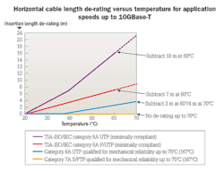
The graph shows the horizontal length de-rating for minimally compliant Category 6A UTP and F/UTP cables. At 60 deg. C (140 deg. F) the standard-specified length reduction for minimally compliant Category 6A UTP horizontal cables is 18 meters. In this case, the maximum permanent link length must be reduced from 90 meters to 72 meters to offset increased insertion loss due to temperature. For minimally compliant Category 6A F/UTP horizontal, the length reduction is 7 meters at 60 deg. C (140 deg. F), which means reducing the maximum link length from 90 meters to 83 meters. Note that the TIA and ISO/IEC profiles from 60 deg. C to 70 deg. C (140 deg. F to 150 deg. F) are extrapolated assuming that the de-rating coefficients do not change and are provided for reference only.
While minimally compliant shielded cabling systems have more-stable performance at elevated temperatures and are better suited to support remote powering applications and installation in hot environments than UTP cabling, the graph also shows the horizontal length de-rating for higher-quality shielded Category 6A and Category 7A cables that are qualified for mechanical reliability up to 75 deg. C (167 deg. F). The length reduction for the higher-quality 6A F/UTP horizontal cable at 60 deg. C (140 deg. F) is 3 meters, which means reducing maximum link length from 90 meters to 87 meters. Furthermore, cables of this quality may be used to support remote powering currents up to 600mA applied to all four pairs up to 60 deg. C (140 deg. F). In this case, the maximum link length must be reduced from 90 meters to 86 meters to accommodate the heat buildup inside the cable bundle.
Due to superior and stable insertion loss performance, fully shielded Category 7A cables qualified for mechanical reliability up to 75 deg. C (167 deg. F) do not require any length de-rating to support remote powering currents up to 600mA applied to all four pairs and all networking applications up to and including 10GBase-T over a full 4-connector, 100-meter channel topology in environments up to 70 deg. C (150 deg. F).
As demonstrated, higher-quality shielded cables qualified for mechanical reliability up to 75 deg. C (167 deg. F) exhibit extremely stable transmission performance at elevated temperatures and require less length reduction than specified by TIA and ISO/IEC standards to satisfy insertion loss requirements, providing the cabling designer with significantly more flexibility to reach the largest number of work areas and devices in converged building environments.
A better patching solution
While TIA and ISO/IEC temperature dependence characterization focuses on the performance of solid-conductor cables, it is well known that the stranded conductor cables used to construct patch cords exhibit significantly greater insertion-loss rise due to elevated temperature than do solid-conductor cables.
To maximize flexibility and minimize disruptions when device moves, adds and changes are made, a zoned cabling solution is the topology of choice for the building automation systems (BAS) most likely to take advantage of remote powering solutions. However, most BAS horizontal connection points in a zoned topology are located in the ceiling or in plenum spaces where high temperatures are most likely to be encountered.
Fortunately, the risk of performance degradation due to elevated temperatures in zone cabling environments can be mitigated by using solid-conductor cords for equipment connections. For Category 6A applications, look for equipment cords constructed from shielded solid-conductor cable that are recommended for support of remote powering applications in environments up to 60 deg. C (140 deg. F). Equipment cords constructed from shielded Category 7A solid-conductor cable that are recommended for support of remote powering applications in environments up to 70 deg. C (150 deg. F) can provide even less risk in these elevated zoned cabling environments.
The future of remote powering applications
The advent of remote powering technology has significantly increased the number of networked devices with surveillance cameras, IP phones and wireless access points driving the market for PoE chipsets today. As the PD market matures, new and emerging remote powering technology continues to evolve to support advanced applications, improved efficiency and increased power delivery. Power over HDBase-T, UPOE and the work of the IEEE 802.3be DTE Power via MDI over 4-Pair Task Force to develop more-efficient power-injection schemes are enabling remote powering applications that will support new families of devices, such as lighting fixtures, high-definition displays, digital signage and point-of-sale devices that can consume more than 30W of power.
All trends indicate that four-pair power delivery is the future of remote-powering technology. As the market for remotely powered IP devices grows and more-advanced powering technology is developed, the ability of cables and connectors to operate in higher-temperature environments and perform under DC load conditions will emerge as critical factors in the long-term reliability of cabling infrastructure used to support PoE and other low-voltage applications that deliver power over twisted pairs.
Choosing connectors and cables that are specifically designed to handle remote powering current loads, associated heat buildup and contact arcing are important steps that can be taken to minimize the risk of component damage and transmission errors. Fortunately, higher-quality shielded cabling products designed to operate under demanding environmental and remote powering conditions are already available today.
Valerie Maguire, BSEE is director of standards and technology at Siemon (www.siemon.com), and is actively involved in industry standards organizations.
Archived CIM Issues

