Connectors a worthwhile option for outside-plant fiber
Some service providers are choosing connectors for cost and flexibility reasons in fiber-to-the-home deployments.
When planning next-generation fiber networks, service providers must determine how to build them for the lowest possible cost and in a manner that creates flexible, reliable, long-lasting infrastructure. In determining the best strategy for achieving these objectives, service providers must make some critical decisions. One of the most important is deciding whether to use splices or connectors when creating junctions in the network.
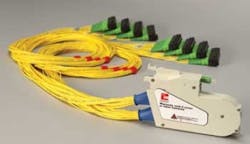
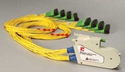
Optical splitters, such as this 1x64 OmniReach Mini-Plug-and-Play Splitter from ADC enable service providers to simplify installation and turnup of fiber-to-the-home service.
For the past decade, as providers have built out their fiber networks, their standard practice has been to use connectors inside the central office to connect fiber network elements. They understand how valuable connector-interface points are when it comes to troubleshooting, reconfiguring the network, and turning up services. Many carriers, however, still use an all-spliced approach from the central office to the subscriber’s premises. They have three primary objections to connectorization.
- The capital-expense savings of a fusion-spliced approach outweigh the operation-expense savings of connectorization.
- Extra connection points within a connectorized approach can affect the loss budget and create additional points of failure in the network.
- Service providers are uncertain whether or not the number of network failures will be large enough to require the additional test-access points that connectorization provides.
In some cases, splicing segments of the fiber network is less expensive than using connectors in terms of initial equipment costs. Many have discovered, however, those upfront savings eventually evaporate as splice-related issues increase operational expenses and reduce the network’s flexibility over time. In fact, a growing trend among service providers worldwide is to use connectorization in order to achieve in the outside plant the same benefits they get in the central office. For example, in early 2008 China’s Minister of Information Industry released the China FTTH (Fiber to the Home) National Standard, which advocates a connectorized approach throughout the network, including feeder cables.
One of the areas in which connectorization’s opex benefits are readily apparent is service turnup. At two network locations in particular—the fiber distribution hub and the fiber access terminal—connector interfaces offer advantages.
In a greenfield application in which there may be an expected take rate of 100%, splicing all the optical splitter outposts to the distribution cables, as well as the distribution cables to the drop cables, may seem to make sense. In reality, not all premises will be occupied, or even built, on day one. Consequently, service turnups will not occur all at once.
In a brownfield or overlay application with a take rate of less than 100%, most service providers prefer to deploy splitters one at a time on an as-needed basis, and to have easy access to the distribution fibers at the access terminals for fast service turnup.
In a splicing scenario the service provider dispatches a technician to splice a single fiber in the fiber distribution hub and fiber access terminal each time a customer requires service turnup. Similarly, splicing forces the service provider to convert all customers during an upgrade service, rather than just those who want the upgrade. Both situations are expensive propositions in terms of equipment, labor requirements, training, and time.
By contrast, using connectorized interfaces at the fiber distribution hub and fiber access terminal simplifies the service turnup and upgrade process. A technician merely plugs the splitter output into the distribution output in the fiber distribution hub, and a drop fiber to the distribution fiber at the fiber access terminal. Service turnups and upgrades are a matter of mating two connectors.
Further, connectorization enables service providers to customize their offerings more easily, quickly, and cost-effectively. In terms of scaling a network, a connectorized approach also enables service providers to transition from a 1x32 to a 1x64 or from one passive optical network to a different passive optical network platform.
Improving flexibility and loss budgets
Although service providers initially rejected a connectorized approach, in part because of concerns about its potential impact on loss budgets, connector-placement options and technology advances in the connectors themselves have persuaded some to change their strategy. It is true that for every connector in a fiber network, there is loss. Yet, importantly, while connectors at certain locations in the outside-plant segment of the fiber-to-the-premises network definitely add value in terms of flexibility, deploying them at every location where fibers meet is not cost-effective. Service providers basically have three options for using connectors in the fiber distribution hub: 1) Provide a full splitter cabinet interface within the fiber distribution hub; 2) Use pigtails from the optical splitter output to connect directly to the distribution fiber ports; and 3) Splice the input to the optical splitter/connectorize the output. We will look at these options one at a time.
Provide a full splitter cabinet interface within the fiber distribution hub. The fiber distribution hub comes loaded with the incoming, factory-terminated feeder fiber routed to the splitter chassis and distribution fibers to the rear ports of the distribution fiber bulkhead. The 1xn splitter module is also factory-terminated, with the splitter input connector mated to the feeder fiber in the splitter chassis. At the time of the service turnup, the technician simply routes a splitter output connector to any of the distribution output ports. Adding splitter modules on an as-needed basis requires the technician to plug the splitter into the next available slot in the splitter chassis. The output connectors are placed in the appropriate “parking-lot” location.
Despite that this option, with completely accessible fibers, offers the greatest flexibility, it has two downsides—added cost and the added signal loss of two mated connectors. The highest typical loss is 0.5 dB.
Use pigtails from the optical splitter output to connect directly to the distribution fiber ports. A technician loads the optical splitters into the fiber distribution hub on an as-needed basis and puts the output ports from each splitter into a “parking lot” configuration within the cabinet. In the parking lot, dust caps protect the connectors until they are assigned, on demand, to customer distribution fibers. This option enables the service provider to:
- Add optical splitters as needed, thereby minimizing upfront equipment costs and maximizing efficient use of the optical line terminal;
- Have ample operating flexibility, further enhanced by the fact that upjacketing on the splitter output-tails protects against damage during the routing process;
- Achieve an optimum balance between cost and operational efficiency by using just two connector pairs and thereby reducing both costs and dB loss.
Splice the input to the optical splitter/connectorize the output. This option addresses the safety issues associated with the higher power required by the video signal to drive the receivers at the customer premises. The analog video signal leaves the central office with relatively high power; it reaches the splitter in the fiber distribution hub with a power level around 20 dBm. This high power level at the splitter input port can create a potential laser eye-safety issue for technicians, but this concern has been resolved by employing a protective splitter shutter adapter.
To eliminate this potential safety issue from the network, a technician can splice the input to the optical splitter. Although less flexible than the two-connector pair option, this option still has a connectorized splitter output for easier test access and on-demand service turnup at the distribution end; reduces cost; and lowers dB loss.
Nevertheless, it may not deliver all the cost savings the service provider wants, simply because a splice technician must be present to add splitters to the fiber distribution hub.
As noted earlier, technological advances also have persuaded many service providers to turn to a connectorization strategy. As fiber-to-the-premises equipment volumes increase, connector providers have significantly improved connector quality and performance in the network. More-stringent performance standards such as the Telcordia GR-326-CORE specification, combined with improved manufacturing processes, have resulted in lower insertion and return loss, automated tuning, excellent endface workmanship, and vastly improved factory-termination methods.
Accessibility for testing
Acknowledging that connectorization provides additional test-access points in the network, some service providers have claimed this characteristic is unimportant. They believed, at least initially, that the number of fiber-network failures is too small to necessitate extra test sites. In the long run, as their fiber networks grow larger and more complex, some service providers have come to recognize that simplified test access is important and in fact is one of the strongest arguments for replacing splices with connectors.
The first and most necessary testing requirement takes place during service turnup. If the network has no connectors, technicians must splice connectors onto bare fibers, perform testing on both ends of the network, then break the fiber. A connectorized approach streamlines this process dramatically.
Regarding ongoing test-access needs, service providers face two tough challenges when trying to isolate faults in the network. The first involves the 1x32 optical splitters in the fiber distribution hub. Typically a technician uses an optical time-domain reflectometer (OTDR) to trace the location of the fault, but OTDR traces are difficult to decipher once the trace hits the 1x32 splitter.
The second challenge arises when only one subscriber has a problem. How does a technician access the fiber to test a network without taking as many as 32 subscribers out of service? When more than one subscriber served by a splitter in the fiber distribution hub reports a problem, the fault likely has occurred somewhere between the optical line terminal in the central office and the fiber distribution hub in the field. In that scenario, a technician can access the network inside the central office to get a good look from the optical line terminal to the fiber distribution hub. But testing the network from the fiber distribution hub to the subscriber requires a truck roll. In this scenario, network design has a significant impact on how quickly a technician can isolate the problem.
If the service provider adds test-access points at the optical network terminal at each premises, the fault-isolation process requires a technician to tap into the network interface device at each individual residence. These interface points may not be easily or readily accessible. However, using the distribution output port in the fiber distribution hub as a centralized demarcation box gives a technician a single location with test access to any fiber for multiple residences, thus allowing easy access to the network between the fiber distribution hub and the optical network terminal.
In cases in which the installers have spliced a splitter into the network, a splice technician must go to the fiber distribution hub, access the appropriate splice between the splitter output and the distribution cable, and connect the OTDR launch cable with a bare fiber adapter or by temporarily splicing a pigtail.
After completing the trace, the technician then must re-splice the splitter output to the distribution fiber—a time-consuming and expensive process.
This process also poses a specific danger to the network. To access the distribution fiber in order to run an OTDR trace, the technician must manipulate several fibers, break those that are to be tested, then splice the fibers back together. Consequently the lengths of available fiber are shorter. There is also the risk, if the technician breaks the fiber to a length that is too short to work with, of stranding some network capacity.
By contrast, placing a connector interface at the splitter output provides easy test access for all the distribution cables. In this case, testing is a matter of locating the suspect distribution fiber on a bulkhead, disconnecting the splitter output pigtail from that port, and plugging in at the OTDR launch cable.
Once the OTDR trace is complete the technician disconnects the launch cable from the distribution port and reconnects the splitter output pigtail, without having to break any fibers or do any splicing. Further, because all the splitter output fibers are connected to a bulkhead, protective jacketing prevents the technician from damaging them during normal handling. Compared to splicing, connectorized fiber in the fiber distribution hub makes it possible for service providers to test the fibers more quickly and easily, at lower labor rates and with less risk to the network.
Long-term performance
Every service provider’s goal in building a next-generation fiber network is to strike a balance between up-front equipment costs and the operational costs involved in long-term network performance. When it comes to the former, connectors may initially be more expensive than splicing. Savvy network planners, however, look ahead to the operational costs incurred by service turnups for individual customers and to the ongoing need for easy test access. Several service providers have discovered that using connectors where they make the most sense in the network justifies the initial equipment costs because it reduces operating expenses over the network’s life.
Tom Huegerich is vice president of global fiber with ADC (www.adc.com). This article is based on, and excerpted from, the white paper entitled “Splices vs. connectorized: A comparison of architectures.”

