Meeting reach objectives for 40/100-GbE channels
These ultra-high-speed transmissions will mandate shorter optical link lengths and require low insertion-loss performance.
The Institute of Electrical and Electronics Engineers (IEEE; www.ieee.org) is developing standard 802.3ba that will support data rates for next-generation 40- and 100-Gbit/sec Ethernet networks. In short-reach applications, such as data centers, multi-lane parallel optics solutions over multimode fiber (MMF) will be specified, where the draft standard currently identifies a MMF reach objective of 100 meters.
The IEEE is basing next-generation transceiver specifications on existing 10GBase-SR technology, but with reduced performance requirements (such as relaxed spectral width and increased jitter tolerance) to achieve cost efficiencies over 10GBase-SR channels. The relaxing of these requirements will result in an increased reliance on fiber media quality to guarantee system performance, and will require network stakeholders to pay greater attention to the capability of the fiber being installed.
Several factors need to be considered when designing and deploying next-generation MMF links. First, although consolidation and virtualization trends are reducing the length and density of cabling in the data center, designers will still need to ensure that 40- and 100-Gbit/sec MMF channels do not exceed reach limits specified by IEEE, since there is a high probability that these channels will be pushed to their performance limits. Second, best-in-class cabling vendors must be able to certify MMF for reliable multi-lane 40/100-GbE performance through accurate characterization of fiber bandwidth.
Fiber bandwidth
In today's high-speed 10-Gbit/sec networks and even more demanding next-generation 40- and 100-Gbit/sec networks, the performance requirements for network infrastructure components are of utmost importance. To ensure faultless network performance and high reliability, network operators and designers must have accurate knowledge of the specification of the components selected and deployed in their networks. For MMF optical channel links, it is important to ensure that the effective modal bandwidth (EMB) of the laser-optimized (OM3) fiber is accurately characterized by the supplier; that optical connectors have low insertion loss (IL); and that the installed cable plant loss is accurately measured and certified by the installer.
Both EMB and IL are critical parameters in high-speed networks and are specified in Ethernet standards, such as 1000Base-SX and 10GBase-SR. The specifications are based on a theoretical link model developed by participating members of the IEEE standards body.
Although not perfect, the model does provide acceptable estimates of maximum channel IL and minimum EMB. It is important to note that many other parameters affect channel performance, including fiber attenuation, inter-symbol interference (ISI), relative intensity noise (RIN), mode partition noise (MPN), and modal noise (MN). IL and bandwidth, however, are the two key parameters related to the physical media that can vary significantly among different suppliers.
Researchers at Panduit Laboratories have found that the correlation between measured channel performance and fiber EMB as measured in accordance with industry standard test methods TIA/EIA-455-200-A and IEC 60793-1-49 is less than ideal. (See Certifying multimode fiber for 100-Gbit/sec Ethernet, CI&M, October 2008.) Results show there is significant uncertainty in system performance as it relates to fiber bandwidth, which can adversely affect channel performance for those links that approach the 300-meter maximum.
Because 10-Gbit/sec Ethernet optical transceivers are designed to support a maximum channel reach of 300 meters, and most channel links within the data center do not approach this limit, this weak correlation has gone unnoticed. For future 40- and 100-Gbit Ethernet, however, transceiver specifications will be relaxed and the maximum reach will be reduced from 300 meters to 100 meters. This 100-meter link length will routinely be pushed to its limit and, in many cases in which long patch cords are used, the limit will be inadvertently exceeded. As a result, 40- and 100-GbE system performance will be compromised and network performance will degrade. Therefore, to ensure network performance, accurate characterization of fiber bandwidth is essential.
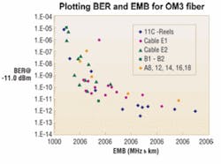
The chart on page 19 plots the measured correlation between bit error rate (BER) and EMB for forty-two 300-meter representative OM3 fibers obtained from a number of suppliers. BER is defined as the ratio of the number of received bits that are in error, to the total number of bits transmitted in time. This test method is the most reliable means of verifying channel performance because it accurately measures single bit failures.
Fibers exhibiting poor BER system performance were also tested, using a commercial 10-Gbit/sec Ethernet traffic analyzer to verify test results. The data indicate that fibers characterized with lower EMB show larger variations in BER performance. For example, for an EMB of about 2,300 MHz•km, the BER can vary by more than three orders in magnitude. In contrast, higher-performance fibers (i.e., >4,700 MHz•km) typically show less variation in system performance.
These results show that fiber quality does not depend on supplier, and so it is important to establish a high confidence that OM3 fiber specified in your data center is accurately characterized and has sufficient bandwidth, and that ample headroom is allocated to EMB to guarantee network performance.
Insertion loss, launch condition
Because the optical loss budget allocated to the fiber media in 10-Gbit/sec and future 40/100-Gbit/sec networks is small (2.6 dB for 10-GbE and 1.9 dB for 40/100-GbE as proposed in 802.3ba Draft 10), both connector IL and loss due to poor bend radius control in structured cabling must be kept to a minimum.
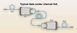
To illustrate the importance of low-loss connectors and the ability to measure low IL accurately, consider a typical channel link found in data centers, as shown in the figure below. In such a link, a switch port transceiver is connected to an array-based MPO preterminated fiber cassette via a patch cord. The fiber cassette may then be connected to another fiber cassette physically located in a different area of the data center or building, establishing a permanent link. Finally, the link is completed with another patch cord, connecting the second fiber cassette to a second switch port transceiver. For 10-GbE, the optical power budget is only 2.6 dB: 1.1 dB for fiber attenuation and 1.5 dB for connector IL. Hence, the average allowable IL for these four mated connector pairs is 1.5db/4, or 0.375 dB per pair.
Insertion loss can be easily measured using a light source, reference launch/patch cord, and a calibrated optical power meter as specified in domestic and international standards, including TIA/EIA-568-B.3 Optical Fiber Cabling Components Standard. But the value of IL strongly depends on the launch conditions, or more precisely the optical power distribution, of the source. Because light sources used for IL measurements produce various modal power distribution when launched into MMF, and the multimode components possess some level of differential mode attenuation (DMA), these standards have traditionally used the coupled power ratio (CPR) parameter as a way of specifying the launch condition at the test interface for accurate and repeatable IL measurements.
CPR is a simple quantitative measurement of the mode power contribution in multimode fibers. Specifically, CPR is defined as the ratio of the total power emitted from the multimode launch fiber to the power emitted out of a singlemode fiber (SMF) when the light from the MMF is launched into the SMF by butt-coupling the two fibers together. The larger the CPR, the larger fractional power at the large radii of the fiber; conversely, the smaller the CPR, the more power is propagating near the central region of the fiber core. For multimode fiber channels, which inherently possess some amount of DMA, it is generally observed that the measured channel IL increases with light source and launch cord CPR.
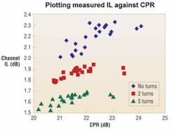
The figure on page 22 (top) plots the measured IL across an optical link over 66 different launch conditions. The link was configured identically to the link shown in the illustration, and each launch condition was characterized by CPR. The data demonstrate that specifying the launch conditions by CPR for making IL measurements may result in large variations in measured channel IL.
In addition to CPR, the effect of bending on measured IL by wrapping the launch fiber around a 1-inch-diameter mandrel is also shown. When measuring IL, it is critically important that the launch fiber does not contain unsupported high-order modes or cladding modes. The data show that when the fiber is not bent around a 1-inch mandrel (no turns), the distribution of IL is consistently high and shifted to larger CPR values. In this case, where no mandrel is used, we see that the repeatability in the measurements is very poor.
From these data, we conclude there is no good quantitative relationship between CPR and IL and, therefore, the launch condition is insufficient to guarantee repeatable and reliable measurements.
When the fiber is subjected to bending by wrapping the launch fiber two or five times around the mandrel, both the IL and CPR significantly decrease, partly because unpredictable leaky highorder modes and cladding modes are more effectively stripped from the fiber core. Hence, adherence to manufacturers' bend-control recommendations will produce more-repeatable results.
For legacy networking applications with larger power budgets, measurement uncertainty due to launch-condition variation did not have a significant impact on channel performance. For 10-GbE and future 40- and 100-GbE networks; however, this IL measurement uncertainty is excessive with respect to the overall power budget and can adversely impact system performance.
Improving IL measurements
To improve the repeatability of IL measurements on installed MMF cable plants, the Telecommunications Industry Association (TIA; www.tiaonline.org) is in the process of defining a much more tightly defined launch condition that will result in IL measurement variability of less than 10% (in dB). Because the DMA of multimode cabling and connectors is largely influenced by the power distribution at large radii, the power in this portion of the launch cord must be tightly specified.
Encircled flux (EF) is a measure, as a function of radius, of the fraction of the total power radiating from a multimode fiber's optical core. Because the complete mode power distribution at any radii can be specified, it is a much better parameter than CPR to define the power distribution at large radii.
The best or target EF to be used to measure IL is a careful balance between overfilled and underfilled launch conditions. An overly high EF at a particular radius essentially underfills the fiber core and, although it may provide highly repeatable results, this launch condition may underestimate the IL and may not be able to discriminate the quality of connectors with high-enough resolution. Conversely, if the EF at a particular radius is too low, the fiber core will be overfilled and thus the IL will be overestimated due to increased levels of DMA. Furthermore, the repeatability of IL measurements in this latter case will be compromised.
A set of EF limits has been drafted through the use of comprehensive theoretical modeling and experimental measurements. The EF limits are defined for all four combinations of operating wavelength (850 and 1300 nm) and nominal fiber-core diameters (50 and 62.5 µm). The targets are only specified at four radial points for 50-µm fiber and five radial points for 62.5-µm fiber. An example set of EF limits for MMF with a core diameter of 50-µm and an 850-nm operating wavelength is provided in the figure below.
Although these EF limits have yet to be adopted in the domestic and international standards bodies, the importance of launch conditions on cable-plant certification has already been recognized and is actively being addressed. As currently proposed in the 40- and 100-GbE draft standard 802.3ba, MMF solutions will support a maximum reach of 100 meters. Although this reach objective might be extended, media-performance concerns will not change.
Because a large number of links will approach this reach objective, with nearly 15% exceeding 100 meters, many links in future high-speed networks will be pushing the MMF performance limit. Therefore, high-bandwidth fibers with additional headroom, as well as certified OM3 cables, will help guarantee channel performance.
Future high-speed, next-generation networks also will have exceedingly small IL budgets. To guarantee accurate characterization of connector IL, manufacturers must have tight control of the test conditions used to certify and guarantee minimum IL when installed. Because poor radius control can add excessive bend loss, thereby degrading channel performance in low-margin, high-performance networks, it is important to observe cable management best practices to ensure high performance across the physical infrastructure. Also, installers should deploy best-in-class low-loss connectors, which have low levels of DMA; these connectors provide additional loss headroom, and also help mitigate cable-plant measurement uncertainties.
Contractors and installers need to be aware of how the elements addressed here contribute to the media performance of next-generation fiber-optic networks. To achieve desired performance levels defined by network stakeholders, it is critical to select vendors that are able to articulate the points of concern outlined in this article and provide guidance on adhering to best practices and procedures.
RICK PIMPINELLA, Ph.D., is fiber research manager, and BRETT LANEb, Ph.D., is a fiber research engineer at Panduit Corp. (www.panduit.com).
Study says 40-, 100-Gigabit networks imminent
A study by Research and Markets (researchandmarkets.com) finds that despite uncertainty over why 40- or 100-Gigabit would ever be needed, the market has awoken to supercomputing clusters that are increasing processing power exponentially, data centers demanding big reductions in latency, and IP backbones whose traffic is still growing 40% annually.
In its report, 40 and 100 Gigabit Networks: Technologies, Markets, Applications, the research firm maintains that, coming out of a decade-long slumber, the market is heading in a direction many could not have imagined—including an InfiniBand standard that didn't exist when the first 10-Gigabit router ports came onto the market.
Each advancement is prompting more questions, says the report, including:
- If video is the killer app, why are large telcos deploying 40-Gigabit router ports in regions where they don't sell IPTV?
- Technology developers are debating modulation technologies. Are customers?
- How will supercomputing center and research network spending compare to traditional telcos?
In addition to forecasts by protocol, industry, and line rate, the study looks at differences in network configurations and how they will impact demand for 40- and 100-Gigabit systems. Key topics include: 40- and 100-Gigabit economics and technology developments; leading industries for 40- and 100-Gigabit deployments; and forecasts.
Companies/organizations mentioned in the report include: Airbus; Altair; AT&T; BT; CANARIE; Ciena; Cisco; ExxonMobile; Force10; GEANT; General Electric; Goldman Sachs; Google; Infinera; Morgan Stanley; National LambdaRail; Nortel; OpVista; Sycamore; TeliaSonera; Tellabs; Teragrid; TW Telecom; U.S. Department of Energy; Verizon; and XO.
