The next generation of on-site fiber-optic termination options
By Rich Megill, AFL
The age when anaerobic epoxy connections were the sole option for field-termination connectors has passed and the next generation of termination products offer more flexibility to meet current and future termination needs. There is no “single” field termination connection method that is perfect for every application. Today several alternatives for field termination of fiber cables are available. The application requirements for fiber termination are very diverse in both inside-plant applications as well as outside-plant applications. Space is more valuable than ever and many times there is little or no available space for splice trays or splice sleeves in housings, enclosures and panels. Additionally, the next generation of field termination options is an excellent choice for upgrading or “cleaning up” a project in a rack environment or enclosures.
These products are very effective repairing or restoring existing connectors on installed active equipment or on new systems where factory cables cannot be used. The introduction of splice-on connectors and self-contained patch and splice modules have expanded the arsenal that companies can use to cost-effectively connect their plant in the field. From temporary restoration links to fiber-to-the-x (FTTx) drop deployments, no-epoxy/no-polish (NENP) connectors are being utilized to increase speed and reduce cost. The new self-contained patch and splice module is a viable alternative to traditional patch and splice fiber management panels while removing the space required for a “splice tray” and reducing the cost of space needed. The major technologies available today accomplish the transfer of optical power within the termination in two ways - a mechanical interface using index-matching gel to join the fibers or a fused fiber splice to join the fibers. This article will document the advantages and limitations of each type of next-generation field termination while introducing new technology products that save time, money and most of all, optical budget.
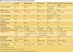
Field termination by definition is the installation of a connector onto the fiber pathway for the purpose of a repeatable, mateable mechanical connection to another fiber or active equipment. A technician has to be able to produce a quality fiber-optic interface in the field or under applications environment. This need has grown exponentially in the past 10 years driven by the increasing demand of access networks and the increased value of rack space. The requirements of the field-terminated optical interface have substantially changed from the days when a single fiber physical polish interface was required. This need has expanded to include small form factor connectors or multifiber connectors with high-bandwidth characteristics may be part of the requirements. Demand has been generated by repair, need to improve fiber routing, fiber system upgrades and consolidation of space to temporary connections. No longer is field termination just for repair or a technician’s occasional process. NENP mechanical connectors are deployed in the inside plant or outside plant environment and many crews are dedicated to using them as part of the FTTx or optical local area network (OLAN) architecture. The customers’ needs have changed and so have the requirements for field termination. The metrics for comparison in this article include cost, time, optical performance, labor skill, tooling investment and termination consistency.
The industry has evolved not just from demand but also from a technology and equipment-cost perspective. It was not long ago that the cost of a fusion splicer was $30,000 or higher. Technology and demand have had a significant impact on the cost and performance of this next generation of fusion splicers giving consistent good results even when using fixed V-groove cladding alignment at a cost of $3k-4k. High-end core-alignment fusion splicers are now in the $10k range. This has removed a significant roadblock by reducing the capital investment to produce quality splices. Technology improvement has also been apparent in the increased performance and acceptance to mass fiber splicing 12 fibers or more.
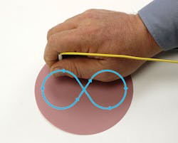
Another area where technology has made high-performance field termination more cost effective has been the cleaver. Typical high-performance cleavers today have a blade life span that brings cost-per-cleave under $0.02. The investment in a high-performance cleaver is recommended as the performance of these new connector systems are directly related to the consistent quality of the cleave that can be produced. When working with a quality cleave, a NENP termination using index-matching gel is a viable solution. These mechanical-type connectors gained a very bad reputation in the mid-1990s when deployed in the outside plant environment. Today’s mechanical systems have significantly improved the retention of the fiber as well as the performance of the index-matching gel.
The final area that has driven changes in field termination has been the increased need for an angled polish connector (APC) endface as the interface. APC interface has become industry standard for FTTx and other outside plant equipment. Finally, the cost of material per termination has decreased significantly as these next-generation termination products have become widely deployed.

Anaerobic (epoxy/polish) - The baseline for the comparisons in this article will be traditional anaerobic field termination. These terminations were accomplished by taking the existing field fiber and adhering it inside the ferrule. Once the epoxy has cured, the technology must scribe and break the fiber stub then polish the ferrule endface with a puck and lapping film. These are low-cost connectors that give stable performance over time and temperature.
Anaerobic connectors are considered to be proven and widely accepted in the industry. These connectors had been the workhorse of the early fiber deployment as good performance resulted when properly installed, but there are performance limitations. The mating endface and performance of the connector was defined in the field by the skill of the technician. Performance of anaerobic terminations are impacted by lapping film material, skill of technician in puck and polish, the shelf life of adhesive and the time spent on each connection to maximize the endface polish.
Anaerobic connector considerations:
- Labor-intense process with inconsistent results (5-7 minutes per termination)
- Connector performance dependent on skill of the technician and quality of the supplied materials
- Limited to produce PC finish; not recommended for APC
- Limited bandwidth application, ≤1G
- Consumables needed and had a limited shelf life
- Require product-specific tools (puck, polish base, scribe, cleaver)
No-epoxy no-polish (NENP) connectors remove field-polishing variable - The next step in the family of fiber terminations is the NENP mechanical connector available in a wide variety of connector types. This system has a physical way to retain the field fiber by compression and meet the fiber retention characteristics while providing a factory-polished endface for mating in the adapter. Location and stability of this mechanical retention is critical to produce consistent performance by this style connector. The use of a precision cleaver to produce the best possible cleave and the tight tolerances of the connector interface allow the optical power to pass from the field fiber to the connector fiber with minimal loss or reflection.
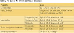
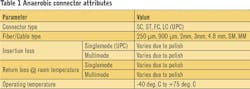
The retention technology used to secure the field fiber stub varies by vendors, using crimp rings to compression. The field fiber is installed to match the field fiber stub to the connector stub, allowing optical transmission through “index-matching gel.” The gel currently used today has been proven stable from at least -50 degrees C to in excess of 250 degrees C, and there is no longer a “lifetime” concern when deployed inside or outside. Temperature has an impact on loss with these connectors, but they remain within the TIA 568-C.3 performance requirements (0 to 60 deg. C) and Telcordia GR-326 requirements (-40 to +75 deg. C).
NENP mechanical considerations:
- Fast termination of fiber cable in field (1-2 minutes)
- Performance is less craft-sensitive and more consistent
- Provides both UPC and APC factory-polished endface in multiple ferrule sizes
- Products to support most common cordage sizes, 900-μm to 4.8mm cordage
- Bandwidth performance ≤10G
- Factory endface ensures consistent mating
- Singlemode and multimode (Om1, Om2, Om3, Om4 Om5)
- No fusion splicer needed
- High-performance cleaver recommended
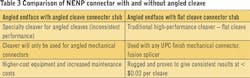
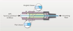
NENP angled polished connectors - The introduction of consistent APC terminations has fed the demand for field-installed APC connectors in FTTx-type projects. Traditional APC performance carries a > -65 dB specification for back reflection, also known as return loss. This level of back reflection is attainable utilizing index-matching gel using an angled cleave fiber mated to an angled cleave connector stub. This is possible when both the stub and the field fiber have an 8-degree cleave. The illustration shows the two connector-stub cleave options in regard to the APC endface.
Production of consistent cleaves with an 8-degree angled cleave is a challenge in the factory and a bigger challenge in the field. Insertion and alignment of these stubs is time-consuming and extremely craft-sensitive. Specialty angled cleavers are sole purpose and require higher maintenance, which adds cost to the termination when considering angled cleave APC mechanical connectors. This “APC” connection back-reflection performance is often not a major consideration in most current FTTx-type deployments as this consideration was minimized by the deployment of digital transmission systems. Consistent performance or an APC endface in an FTTx-type field connection can be produced with traditional high-performance cleavers and give > -55 dB for back reflection, allowing hardware vendors to continue to use the outside plant default standard APC connection.
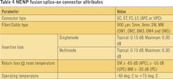
The variables of field deployment include temperature change, performance variation due to factory fiber characteristics, quality of field fiber with regards to quality of fiber, tools and termination process. With all the variables when defining a mechanical connector, the industry has been able to consistently meet the insertion loss requirements of TIA-568-C.3 standard of 0.75-dB max, ITU-T G.671 standard of 0.05-dB max and Telcordia GR 326 standard of 0.4-dB max per mated pair. Individual optical performance needs must be addressed with the specific mechanical connector manufacturer to ensure a robust optical plant is built.
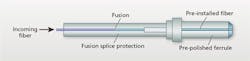
Fusion splice-on connectors remove additional variables, add strength - A wide variety of splice-on connectors are now available for use in the field and retain a consistent splice loss and return loss over temperature and time. These connectors retain the performance of a splice-on pigtail without the need to store a splice sleeve and are the most robust, consistent option for field-installable fiber connectors.
A fusion splicer and high-performance cleaver are needed to produce this field termination. Once terminated and installed, the splice-on connector provides a connection that closely approaches a factory termination with the addition of the optical loss of the fusion splice added to the connector insertion loss. A very predictable and consistent insertion loss and back reflection can be produced as the fusion splicer will verify cleave angle and approximate splice loss. This is much less dependent on craft skill as the fusion splicer will perform initial pass/fail analysis of the fiber stubs and cleave angles before splicing.
NENP fusion splice-on connector considerations:
- Fast termination of fiber cable in the field (2-2.5 minutes)
- Performance is more stable with the addition of the fusion splice
- Provides both UPC and APC factory-polished endface in multiple ferrule sizes
- Products to support most common cordage sizes 900-μm to 4.8 mm
- Bandwidth performance 10G and higher
- Singlemode and multimode (Om1, Om2, Om3, Om4)
- Fusion splicer needed (cladding alignment is acceptable)
- High-performance cleaver recommended
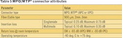
MPO/MTP® connector offers strength in numbers - Taking the strength from the fusion splice type connector and expanding its flexibility for field deployment brings us to a field-installable multi-fiber connector, the MPO (multi-fiber push on). This connector offers the same benefits as a single fiber fusion splice-on connector but terminates up to 12 fibers per connection. This type of connector helps with restoration, repair and upgrade projects of existing MPO networks. The factory endface and fusion spliced optical path produce a solid alternative for field termination. The MPO termination has been growing and will continue to grow with fiber consolidation and high-speed bandwidth connections.
Today 40-, 100, and 400-Gbit connections utilize parallel transmission that requires a 12- or 24-fiber MPO connector terminated with specified pinouts for bonded independent transmission legs. The demand for MPO connection will be agnostic to the technology used in the transmission. From Bidirectional (BiDi) devices to short wave division multiplexing (SWDM) to Gigabit Ethernet transport, an MPO connector will be used to provide simultaneous fiber connect and disconnect capability. As this industry grows, the need for reliable field-installable connectors will grow.

Multiple fiber termination splice-on connector considerations:
- Fast termination of up to 12-fiber cable in field (increased time if installing a connector on LT cable)
- Performance is stable with the addition of the mass fusion splice
- Accommodates ribbon or 3-mm round cordage to terminate
- Provides both UPC and APC factory-polished endface in multiple polarities
- Allows polarity and fiber designation to be defined onsite (very useful for upgrade scenarios)
- Bandwidth performance 10G and higher
- Singlemode and multimode (Om1, Om2, Om3, Om4, Om5)
- Mass fusion splicer needed (cladding alignment is acceptable)
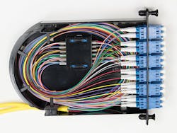
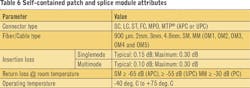
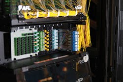
Self-contained patch and splice modules … the options continue - A variation of field-installable termination continues into a self-contained field-installable patch and splice module. Field-installable modules use a traditional pigtail splice to adapter; however, the need for factory pretermination is removed. This is extremely beneficial where limited space or a small footprint fiber termination is needed.
By removing the need for a separate splice tray, the footprint needed is decreased for fiber management and has significant cost impact where lease price per square foot is a consideration. Large splice shelves in racks are no longer needed with this type deployment and it removes the need to factory order preterminated product providing additional flexibility in many types of deployments. Each module will be housed in an industry-standard footprint, for example LGX-118 and allow up to 24 small form factor terminations in a single self-contained unit.
Because this module is self-contained, patch and splice, it is a cost-effective solution when adding a circuit to an existing fiber rack system or colocation type deployment. These are truly a pigtail splice and offer traditional pigtail performance for the termination.
Self-contained patch and splice module considerations:
- Fast termination of up to 24-fiber cable in field (increased time if installing a connector on LT cable)
- Reduced rack space needed as patch and splice are self-contained
- Provides both UP and APC factory-polished endface in multiple polarities
- Allows polarity and fiber designation to be defined onsite (very useful for upgrade scenarios)
- Bandwidth performance 10G and higher
- Singlemode and multimode (Om1, Om2, Om3, Om4, Om5)
- Fusion splicer needed (cladding alignment is acceptable)
As the needs of our fiber-optic network continue to grow and expand, the tools and material options for building and repairing this network will evolve. There is no single type of field-installable termination that will serve every application encountered. The new next generation of field terminations offer cost-effective, reliable field termination, which can impact your bottom line by:
- Increasing the capability of a fiber technician’s abilities to terminate in the field when needed - in house or contracted;
- Providing consistent results with limited variation due to technician training or skill;
- Reducing the labor and/or material cost of field installation of fiber-optic connections;
- Providing additional methods for fast restoration of service;
- Giving factory endface performance termination on cables terminated in the field.
When deciding which path is right for you, it is imperative to verify the optical headroom in the design to take full advantage of these technologies. Multiple vendors offer many products, from standard use to high-performance low-loss. Pick the product and technology that meets the needs of your fiber network. Many times there is no one perfect solution. It may be advantageous to deploy more than one type of field-installable termination for the success of your network.
MTP® is a registered trademark of US Conec.
Rich Megill is a senior application engineer for AFL’s Cable and Connectivity division and supports the service-provider and enterprise markets. He works closely with AFL’s engineering team and customers to produce integrated fiber-network solutions for both inside and outside plant applications. Megill has more than 32 years’ experience in fiber-optic technology and is responsible for AFL solutions ranging from FTTx design and fiber management to outside-plant splicing products with multiple types of cable transport.