Cabling the spine-and-leaf network switch fabric
By Mustafa Keskin, Corning Optical Communications
As the size of networks grew during the last decade, we saw a shift from classical three-tier network architectures to a flatter and wider spine-and-leaf architecture. With its fully meshed connectivity approach, spine-and-leaf architecture provided us the predictable high-speed network performance we were craving and also the reliability within our network switch fabric.
Along with its advantages, spine-and-leaf architecture presents challenges in terms of structured cabling. In this article we will examine how to build and scale a four-way spine and progress to larger spines (such as a 16-way spine) and maintain wire-speed switching capability and redundancy as we grow. We will also explore the advantages and disadvantages of two approaches in building our structured cabling main distribution area; one approach uses classical fiber patch cables, and the other one uses optical mesh modules.
A brief history
Since its arrival in the 1980s as a local area network (LAN) protocol, Ethernet, with its simple algorithm and cheaper manufacturing costs, has been the driving force behind the data center and internet evolution. An Ethernet switch looks into each and every package it receives before it switches it. It only opens the outer envelope to read the Layer 2 address without worrying about reading the IP address. This allows an Ethernet switch to move packets very quickly.
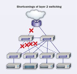
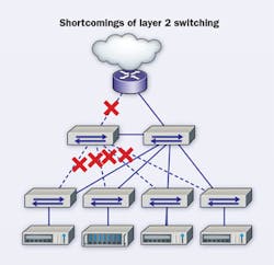
Despite its efficiency, Ethernet also has some shortcomings when the network size grows. In a network consisting of multiple Ethernet switches, in order to stop broadcast packages such as address resolution protocol (ARP) requests from flooding and looping around the network, a technology called spanning tree protocol (STP) is used. STP blocks redundant links to prevent loops happening in the network. Networks running on STP technology use the redundant links as failover in the event of a main link failure. This provides resiliency to the infrastructure at the cost of half the utilization of the available bandwidth.
We built networks with spanning-tree logic for a very long time until we encountered new problems. The first problem was that we were mostly limited with a dual core network that does not allow room for growth (in order to serve an expanding number of customers, our networks needed to grow accordingly). The second problem was latency. If we have a big network, we normally divide them into smaller networks which we call virtual LANs (VLANs). This results in different latency for different types of data traffic. The traffic that flows through the Layer 2 network within a single VLAN has a different latency compared to traffic flowing between different VLANs crossing through the Layer 3 core.
Introduction to spine-and-leaf fabric
Most of modern day e-commerce, social media, and cloud applications use distributed computing to serve their customers. Distributed computing means servers talking to servers and working in parallel to create dynamic web pages and answers to customer questions; it requires equal latency. Having to wait for results can create unhappy customers. We need a network architecture that can grow uniformly and can provide uniform latency for modern applications.
The solution to these problems came from a network architecture which is today known as spine-and-leaf fabric. The idea has been around since 1952 when Charles Clos first introduced the multistage circuit-switching network, which is also known as Clos networks. The backbone of this network architecture is called the spine, from which each leaf is connected to further extend network resources. The network can grow uniformly by simply adding more spine or leaf switches, and without changing the network performance.
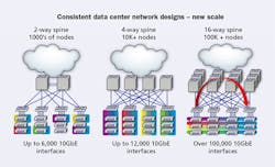
The spine section of the network grows horizontally, which restricts the layers of the network to two layers compared to traditional Layer-3 architecture. For example, with a two-way spine we can build networks that can support up to 6,000 hosts, and with a four-way spine we can build networks up to 12,000 hosts, and with a 16-way spine we can go over 100,000 10-GbE hosts.
Secondly, all leaf switches are connected to every available spine switch in the fabric. This fully meshed architecture allows any host connected to any leaf to connect others using only two hops, which is switch-to-switch connection. For example, leaf 1 to spine 1 and spine 1 to leaf 10. Because an entire spine layer is built in a redundant fashion (in case of a spine or leaf switch failure), alternative paths and resources can be utilized automatically.
The basic rules of building spine-and-leaf networks are as follows.
- The main building blocks are network leaf switches and network spine switches.
- All hosts can only be connected to leaf switches.
- Leaf switches control the flow of traffic between servers.
- Spine switches forward traffic along optimal paths between leaf switches at Layer 2 or Layer 3.
- The uplink port count on the leaf switch determines the maximum number of spine switches.
- The spine switch port-count determines the maximum number of leaf switches.
These principles influence the way switch manufacturers design their equipment.
Closer look into a spine switch - If we look into a typical spine switch, at first sight we notice multiple expansion slots, such as four or eight that accept different line cards, which are used for connecting to leaf-switch uplinks. Line cards can come in different flavors such as 36x40G QSFP (for 40-Gig) ports or 32x100G QSFP28 (for 100-Gig) ports. Quad small form pluggable (QSFP) and QSFP28 ports are empty, so necessary transceivers have to be bought separately in the form of either singlemode or multimode transceivers or active optical cables (AOC), or twinaxial cables. General rule is that the number of available ports on the spine switch determines the number of leaf switches you can connect to the spine, thus determining the maximum number of servers you can connect to the network.
Next, we see supervisor modules that monitor and manage the operations of the entire switch. Power supplies provide redundant power, and at the backside of the spine switch we generally have fabric modules that mitigate traffic flow between different line cards. Evenly distributing leaf-switch uplink connections among line cards on the spine switch can dramatically improve the switching performance by reducing the amount of traffic flowing through the fabric module.
This increases end-to-end package delivery times, which means delays, and requires procurement of additional fabric cards, which means additional cost. In the coming sections we will discuss how to solve these problems with cabling.
Closer look into leaf switch - When it comes to the leaf switch discussion, the main consideration is the number of uplink ports, which defines how many spine switches one can connect to, and the number of downlink ports, which defines how many hosts can connect to the leaf switch. Uplink ports can support 40/100G speeds and downlink ports can vary from 10/25/40/50G depending on the model you are planning to use.
Scaling out a spine-and-leaf network with redundancy and at wire-speed switching - Let’s consider this situation. We have two spine switches and there are four line cards on each spine switch, but we only have four uplink ports on each leaf switch. Is it possible to distribute these four uplinks among eight line cards in order to maintain redundancy and wire-speed switching?
If we are using 40G SR4 transceivers, we know that they are actually made up of 4x10G SR transceivers, and a 40G-SR4 port can be treated as four individual 10G ports. This is called port breakout application. Port breakout allows us to scale out and have redundancy as we grow networks in ways we traditionally cannot do. For example, it’s possible to break out 2x40G SR4 transceivers into 8x10G ports, and easily distribute them over eight line cards.
Crossconnect with traditional port breakout - To represent this, let’s create a 10G crossconnect using Corning Edge8 solution port breakout modules. We can breakout all 40G QSFP ports at the spine layer using Edge8 solution port breakout modules. We can do the same exercise with the leaf switches. Now, we can simply make an LC patch connection between respective leaf switch and spine switch. By doing this, we can breakout all 40G ports and distribute them over four different line cards.
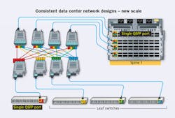
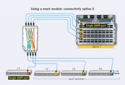
Redundancy is maintained, which means if you lose one line card, you only lose 25 percent of your bandwidth. We maintained line-speed switching by making sure that all leaf switches are represented on all line cards, thus no traffic needs to go through the vertical fabric module. Every yellow highlighted port represents a single 40G QSFP port.
Is this the most elegant way of doing things? No. This is called building new networks using old tools.
Crossconnect with mesh module - Is there a better way to do this? Let’s consider a mesh module. This mesh module is connected to the spine switch on one side and to the leaf switch on the other side. Spine-side ports are connected to individual line cards on the spine switch. And every time we connect a leaf switch on the leaf side, it automatically breaks out that port and shuffles them across the spine ports on the mesh module, which are already connected to separate line cards.
We do not have to do any LC-to-LC patching. We still achieve the shuffling we were trying to do in the previous scenario, we have full redundancy, and we can get full performance out of our switches.
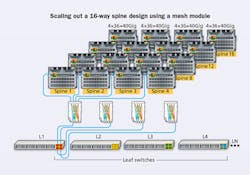
Expanding the fabric with mesh module - Going from two-way spine to four-way spine is easy. We simply use one mesh module per spine switch, and distribute each 40G uplink from leaf layer over four line cards on each spine switch.
Going beyond four-way spine switch is easy using mesh modules. We will connect the spine side of the mesh module to other spine switches. We are losing the line-card level redundancy and switching efficiency, but we gain more redundancy by distributing risk over 16-way spine. At this point, we should also invest in fabric modules, because we will have a case that will have different leaf switches on different line cards in the same chassis. With this final expansion, we can have a network that is four times bigger than a four-way spine.
Using mesh modules has several advantages. We can lower connectivity costs by 45 percent. By replacing LC patch cords with MTP patch cables, we can reduce congestion by 75 percent. Because we do not need housings to do the LC breakout and patching, we can realize a 75-percent space savings at the main distribution area (MDA).
History has shown us that with every new development we had to invent new ways of doing things. Today, the industry is moving toward spine-and-leaf fabric, and switch manufacturers have advanced switching systems designed for this new generation of data center switch fabric. A basic requirement for such fabrics is to build a mesh-structured cabling module that can allow you to get the best out of your fabric investment.
Meshed connectivity for spine and leaf can be achieved using standard MDA-style structured cabling, which we can compare to building new things using old tools. Using mesh modules as a new tool to build next-generation networks can dramatically reduce the complexity and connectivity costs for your data center fabric.
Mustafa Keskin is market development manager for Corning Optical Communications Europe-Middle East-Africa (EMEA).
