Additional cabling practices for open offices
George V. Weller
Steelcase Inc.
Part of the horizontal cabling in typical North American open offices runs through furniture pathways. This makes moving the furniture difficult because it usually involves replacing the entire horizontal cabling run. Meanwhile, user organizations are demanding offices that are much easier to reconfigure.
Two new cabling practices for open offices were recently published in the Telecommunications Industry Association`s (tia--Arlington, VA) telecommunications systems bulletin tsb-75, "Additional Cabling Practices for Open Offices," to address these issues. These practices are intended to make open- office reconfiguration less difficult. They are also expected to be useful in the context of harmonizing with iso/iec 11801, the international generic cabling standard.
Churn and flexible layouts
Market pressure for higher productivity, lower cost, and faster response to customer needs has led to high rates of reorganization and rearrangement in offices, also called "churn." Business organizations today also often retain substantial numbers of temporary employees to complete special projects more quickly, and require that facilities be made available for their use.
Many critical specialists are shared, moving from project to project quickly, as needed. Computer-assisted collaborative work compounds the difficulty, as the participants now bring portable computers and other furniture along with them. They expect to find network and power connections ready, but these connections must be unobtrusive when not needed.
Work teams often need to gather on short notice for ad hoc meetings. Because conference rooms are seldom available on short notice, the team`s own space must be rearranged for the meeting. If the normal configuration is for individual work, this involves moving walls or panels.
The increasing importance of knowledge work--the acquisition, analysis of, and action upon knowledge--creates conflicting requirements for individual privacy for concentrated work, and open, interactive spaces that facilitate instant face-to-face communications. Again, movable walls or panels are required.
Clearly, one can reduce the cost of reconfiguring offices by reducing needed changes to cabling runs through building pathways. And if changes can be made more quickly, there are obvious savings in reduced downtime. It has also been suggested that the biggest cost in reconfiguring offices is the lost productivity when a needed configuration is delayed or forgone because of cost, downtime, or some similar factor.
A strategy for modern workspaces
Creating a remateable connection where cabling leaves building pathways and enters furniture allows the portion in the furniture to be moved or replaced without disturbing the building portion. If users can make these changes themselves, rather than waiting for facilities staff, delay time can be reduced. This is a controversial issue, however. Many see problems with user administration, which may involve unskilled users and loss of control by facilities managers. The final preference seems to be a matter of corporate and individual style.
It is said that when Alexander Graham Bell announced his intention to give everyone in the country a telephone, he was told that such a thing was impossible because everyone would have to be a telephone operator. But after the dial telephone was invented, that`s exactly what happened. If networks and infrastructures were easy enough to manage, we could all be network managers and not have to wait for facilities staff.
Experience in electric and telephone distribution has shown that one can often reduce costs or improve system flexibility by placing some of the distribution equipment closer to the end-user. Although tsb-75 does not go far in this direction, the trend is clear.
Provisions of tsb-75
The tia`s TR-41 committee has been working for some time on the PN3398 project, which has produced tsb-75. This document addresses flexibility and cost issues of horizontal cabling by offering the multi-user telecommunications outlet assembly (mutoa) and the consolidation point (CP)--two new cabling practices. Both of these practices try to reduce the need to replace horizontal cabling when open offices are changed.
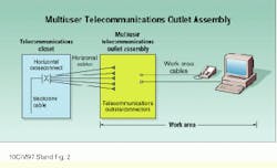
The mutoa collects all the outlets for a furniture cluster--a contiguous arrangement of furniture--into one location. Work-area cables go directly from the mutoa to the end-user equipment. No additional outlet is present in individual workspaces. This approach is most attractive when it is desired to make all furniture easily movable. In such cases, it is sometimes difficult to identify individual workspaces or even fixed objects upon which to mount outlets.
Furniture can move freely around the mutoa, which is mounted in a semi-permanent enclosure attached to the building structure. Work-area cables used with a mutoa may be up to 20 meters long, if horizontal cabling is shortened to compensate--for example, from 90 to 70 meters, for 20-meter work-area cables.
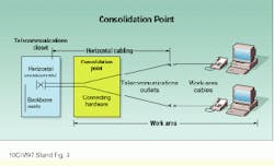
The CP provides an interconnection between horizontal cables in building pathways and horizontal cables passing through work-area pathways (such as in furniture) to telecommunications outlets. Work-area cables then connect outlets to terminal equipment as usual.
Like the mutoa, the CP is housed in a suitable enclosure. It consists of connecting hardware but must be an interconnect, not a crossconnect--that is, no patch cords are permitted. The CP makes sense where there are individual workspaces formed from movable partitions or panels.
CPs and mutoas are essentially interfaces between the building and the work area. Accordingly, planning and installation must be a collaborative effort among architecture, interior design, telecommunications, and client user groups, with all skills involved as early as possible. In North America, this is much more difficult than it sounds. The building industry is so fragmented that it is difficult to arrange for, or require, collaborative work. It is important to begin early enough to make sure that this requirement is in the specifications, on the description of work, and in the contracts.
Untested cabling strategies should be mocked up with real cables and connectors, and on real furniture. Planners should work with furniture vendors to ensure that cable capacities, bend radii, and termination spaces are adequate and accessible. In some cases, installation sequencing may be important.
Performance of mutoas and CPs
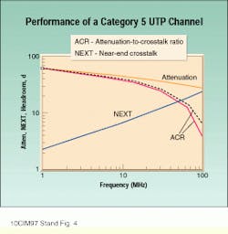
The performance implications of the CP should be negligible when compared with the standard tia channel-performance model in ansi/tia/eia-568a, Annex E, which includes a transition point (TP) between round cable and flat undercarpet cable. The TP and CP have the same performance impact because there is only one generic specification for connecting hardware. The CP or TP reduces headroom--attenuation-to-crosstalk ratio--at 100 megahertz by about 2.5 decibels. This still leaves 3.5 dB of positive headroom, assuming worst-case components combined in the least favorable way.
tsb-75 allows the use of work-area cables longer than the customary 3-meter limit. The attenuation of stranded cable stock used in work-area cables is about 20% greater than that of the solid stock used in horizontal cabling. Accordingly, longer work-area cables are allowed only where horizontal links are correspondingly shorter, so that maximum channel attenuation does not exceed specified values.
Practical issues to consider
Some practitioners have expressed concern about the risk of "lost CPs" in the ceiling, after having had similar experiences with zone cabling. If the practice of extending a cable run in building pathways by adding a CP and some more cable is adopted, there is a risk that the process might be repeated, leading to multiple CPs and declining performance. tsb-75 recommends that cabling downstream of a CP be in pathways in the work area--defined as the place where people work--and not in building spaces such as floors or ceilings. Although this is not a definitive requirement, it should minimize the problem of lost CPs if the spirit of the document is followed. The practice is recommended rather than required, in part, because there seems to be less of a problem with CPs in access floors than with ceilings.
Users of a mutoa need to make sure that each piece of equipment is plugged into the service and that the maximum length of jumper permitted by the horizontal cable length is not exceeded. Labeling conventions are suggested by tsb-75 to deal with these concerns.
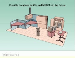
Locations in an open office where a CP or mutoa might be placed include utility columns attached to furniture panels, overhead storage cabinets, enclosures at floor level, and free-standing utility columns. Mobile furniture is probably best served by a mutoa secured to a building structure. Outlets on mobile furniture would require it to be tethered, destroying its mobility. Floor locations can support mobility where really needed, but they create aesthetic problems and present a hazard if located where people can trip on cords. Cables downstream of the mutoa are typically in pathways on desks, tables, or storage areas.
Future directions
What`s next? It should be evident that the next thing people will want to move is the utility column. And, of course, they`ll want to do it themselves, rather than wait for facilities staff. Creating a quick-disconnect for the mutoa would be difficult using the present standardized 4-pair connectors. Twenty-five-pair connectors have only recently attained Category 5 performance and have not yet been standardized. Will the cabling industry support this need, or will people just go wireless?
Some organizations with many competent users and heavy usage patterns have already begun to install full crossconnects and active equipment in the work area. As the equipment becomes easier to use, this trend will doubtless become more prevalent.
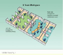
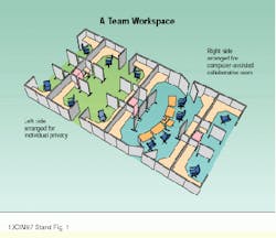
The space on the left is arranged for individual privacy. On the right, the same furniture has been arranged for computer-assisted collaboration. Power and telecommunications connections are needed in what is an aisle in the arrangement on the left.
The mutoa collects all the outlets for a furniture cluster into one location. Work-area cables go directly from the mutoa to the end-user equipment. No additional outlet is present in individual workspaces.
The consolidation point provides an interconnection between horizontal cables in building pathways and those passing through work-area pathways to telecommunications outlets. Work-area cables then connect outlets to terminal equipment as usual.
The graph shows the channel attenuation and crosstalk curves for the standard channel model as a function of frequency. The solid curves are from the tia/eia-568a standard model. The upper, dashed attenuation-to-crosstalk ratio curve is measured without consolidation point or transition point.
Locations in an open office where a CP or mutoa might be placed include two sizes of utility columns attached to furniture panels at left rear. A panel near the tall utility column has an overhead storage cabinet with rear access to cable pathways. A fat panel is shown at rear center with surfaces removed, revealing interior space and cable trays. A local server cabinet with cable distribution frame is at right rear. All of these can accommodate either CPs or mutoas. Each requires access to furniture and building pathways. A free-standing utility column with mutoa is indicated at front center.
George V. Weller is involved in research and development for modular furniture manufacturer Steelcase Inc. (Grand Rapids, MI).
