Charles Schwab invests in its cabling infrastructure
Charles Schwab invests in its cabling infrastructure
Placement and design of telecommunications closets help financial-services company meet current and future user needs.
Robert Y. Faber, Jr.,
The Siemon Co.
The Charles Schwab Corp., headquartered in San Francisco, CA, has been a financial-services provider since 1971. To serve its client base of more than four million customers worldwide, the company operates 245 branch offices in 47 states. Last year, nearly 10,500 employees pro-cessed more than 97 million telephone calls, and customers placed more than 21 million stock trades.
In 1995, the company realized that its Phoenix Regional Call Center would not be able to handle anticipated growth. So, Schwab decided to vacate the buildings it leased in the Phoenix, AZ, area and purchase a 25-year-old building located in the desert foothills of Squaw Peak.
Previously owned by American Express, the two-story structure contained about 170,000 square feet of usable office space on each floor. Because of the building`s size, Schwab knew that it had to pay special attention to the design and placement of telecommunications closets (TCs). Before they could be installed, however, the building needed to be renovated.
The renovations took place in several stages over nearly seven months. First, the building was gutted, and all obsolete building materials--such as flooring, interior walls and fixtures, ceilings, and utilities, including heating, ventilating, and air conditioning, power, telecommunications cabling, and lighting--were removed. Anything that could be salvaged and reused was retained. The building was then rebuilt, with reconstruction completed in four phases, allowing sections of the building to be occupied while demolition was going on in other sections.
Today, the newly remodeled building, known locally as Schwab Peak, contains approximately 1200 employees--80% of whom are telephone representatives--with a total capacity for 1800. The primary function of the staff is to support the Phoenix Regional Call Center.
Special team selects cabling system
Clint Chron, senior systems administrator for Schwab, assembled a team of qualified staff members to design the telecommunications cabling infrastructure to support this business unit: Colleen Peacock, voice systems infrastructure; Mark Gringle, network systems infrastructure; Keith Anvick, network engineering; and Dave Elya, an electrical engineer from a private firm.
The first stage of the design involved assessing structured cabling system providers, such as The Siemon Co. (Watertown, CT) and Lucent Technologies (Murray Hill, NJ), and then evaluating installation contractors, one of whom would be hired to install the cabling system. The mission of Chron and his team was, first, to design the cabling infrastructure based on both current needs and anticipated growth and, then, to select the best cabling system available and hire the installation expertise needed to ensure that anticipated system performance would be achieved.
"What was essential for this project," says Chron, "was that we had an application-independent structured cabling system that would provide exceptionally high performance while complying with recognized standards."
According to Chron, selecting cabling-system hardware and cable was not difficult. "Schwab had experience with different cabling systems and cabling installation companies. The team found that there were many systems available, and the accompanying quality of installations also varied," he explains. "We had to keep in mind, however, that we needed a structured cabling system that would meet Schwab`s desire for long-term reliability."
The Siemon Cabling System and the Lucent Systimax structured cabling system had been installed during the previous 12 months at two other Schwab locations, and Schwab was satisfied with the performance of both. On the basis of the selection criteria of the team assembled by Chron, a Siemon-based system was selected for Schwab Peak. Category 5, 4-pair CommScope Ultra 5504 was chosen for the voice and data horizontal cable. Twisted-pair, Category 3, 300-pair armm cable was chosen for voice-backbone cabling. Lucent supplied 24-strand 62.5/125-micron multimode Accumax optical-fiber cable.
Chron`s team then set out to find a contractor. After an extensive request-for-proposal process, the team selected Teknon (Phoenix, AZ) to install and maintain the system.
Designing the system
Establishing a design for the cabling system began with the designation of the equipment room and the main crossconnect. Overall, the telecommunications cabling system design involves nine crossconnect cabling locations, one of which serves as the main crossconnect and equipment room. This 10,000-square-foot room contains the building entrance cabling from Schwab`s two local exchange carriers--US West and Teleport Communications Group--and all of the voice and data systems and equipment necessary to support the business unit`s operation.
The eight smaller TCs located throughout the structure distribute horizontal cabling and route backbone cabling to the main crossconnect. No cabling connectivity was planned to run directly between the TCs. Because closet locations were planned at the start of the design phase, pathways had been conveniently installed to support the needed cabling connections.
Each work area in the building is served by horizontal cabling that consists of two Category 5, 4-pair cables for data and two for voice services. For backbone cabling, each TC is attached to the main crossconnect with eleven Category 3, 300-pair cables, as well as four CommScope Category 5, 25-pair unshielded twisted-pair (utp) cables and one Lucent 24-strand, 62.5/125-micron multimode optical-fiber cable.
To design a crossconnect system for each of the TCs, different distribution frames were used for horizontal and backbone cabling. The horizontal cabling design included one Siemon xlbet frame--23 inches wide and 7 feet high--with twelve 300-pair S110 wiring bases. This frame can support up to 864, 4-pair outlets. With two 4-pair outlets per work area, that is a total of 432 work areas supported. The backbone cabling design used the same frame, which can support up to 12, 300-pair cables.
Crossconnections from the horizontal cabling field to the backbone cabling field were provided on a one-to-one basis. Each horizontal Category 5, 4-pair cable is crossconnected to a 4-pair portion of an adjacent 300-pair cable terminated on the backbone cabling field. This crossconnection method provides full accessibility to the telecommunications voice services provided by the Siemens 9751 pabx, Aspect acds, and nicelog voice logger systems in the computer room, which serves as the main crossconnect and equipment room.
Data-grade crossconnections used 25-pair, Category 5 utp cables because data service signaling may have been marginal if carried over the 300-pair, Category 3 cables. These data services include low-speed Asynchronous Transfer Mode data of 19.2 kbits/sec, 56 kbits/sec, and primary-rate Integrated Services Digital Network.
In addition, each of the eight TCs contains two cisco Catalyst 5000 layer-two switches (bridges), which have 50-pin telecommunications connector interfaces. These bridges are currently switching 10Base-T Ethernet, with an upgrade to 100Base-TX in the horizontal cabling anticipated in the future. These devices are cabled with Category 5, 4-pair cables to fiber-optic transceivers, which provide connectivity back to the main crossconnect via the Lucent 24-strand optical-fiber backbone cable. Each 50-pin connector is cabled by a Category 3, 25-pair connectorized cable to the back of a Category 5, 48-port high-density patch panel. These patch panels are crossconnected to patch panels on an adjacent rack by 4-pair, Category 5 crossconnect patch cords. The backs of these panels are cabled with Category 5, 4-pair cables, which serve the work areas close to each TC. Each work area receives two 4-pair Category 5 cables, with connectivity back to the active devices.
Telecommunications closet provisions
The design criteria for the eight telecommunications closets centered exclusively on rack-mounted cabling. The closets do not contain plywood walls. In addition, the doorways to the TCs are lockable for security, open inward, and are 36 inches wide to accommodate the equipment.
The lighting requirements for each TC were met with a set of eight fluorescent double-bulb fixtures, which were four feet long and located approximately nine feet above the floor. They were positioned so they would not shed light directly over the racks. Instead, the light shines on the front and back sides of the racks.
The power requirements were met with eight 120-volt, 20-amp branch circuits. Four of the branch circuits were dedicated to one electrical service panel, while the other four were dedicated to a second service panel.
Ladder rack was used throughout each of the telecommunications closets to distribute the cables terminating on the racks. In the first- and second-floor closets, the 24-strand fiber, 300-pair copper, and 25-pair copper backbone cables exit the closets by sleeves or slots near the ceiling. Horizontal cabling exits the first-floor closets by access floor or under-floor duct, while the second-floor closets distribute horizontal cabling by sleeves or slots near the ceiling. In some cases, the horizontal cables then enter the under-floor duct to serve open-office work areas. Each section of ladder rack is grounded with a 6 AWG stranded bonding conductor. These conductors attach to a telecommunications grounding busbar in each closet. The busbars are bonded to the telecommunications main grounding busbar located in the computer room.
Each penetration of a floor, wall, or ceiling for telecommunications cabling is firestopped using a locally approved firestop method such as firestop pillows or various intumescent putties. Each closet contains a wall-mounted telephone, a 4 x 5-foot white board, a fire extinguisher, and trash container, as well as a dry sprinkler system for fire suppression.
Colooding was used to differentiate cables for voice and data applications. In the horizontal, blue denotes cables for data applications, and white represents voice applications.
Horizontal cabling and the work area
To meet user needs in the work area, the media provided were two 4-pair, Category 5 cables for voice services and two 4-pair, Category 5 cables for data. One quad outlet was installed in each modular furniture unit, by Haworth (Holland, MI), and two quad outlets were placed in the fixed office spaces and conference rooms. Two additional quad outlets were put in resource areas where fax machines, printers, and other peripheral equipment was located. As a minimum, one 4-pair, Category 5 outlet provided local area network access in each work area. Some locations also used the second data outlet for a printer.
For voice, one 4-pair, Category 5 outlet was provided for either an Aspect acd port or a Rolm private branch exchange port (although usually not for both). In a work area equipped with an Aspect port, a second voice port was added for the analog voice logger equipment, which requires a single wire pair.
Siemon Co. splitters were used for the two voice jacks when they were needed. Applications that share a single 4-pair outlet via a splitter include analog modems, fax machines, and RS-232 data ports.
A 100-Mbit/sec backbone carries 100Base-TX on 4-pair, Category 5 cabling. It connects the cisco switches in the TCs back to the switches in the computer room. Two cisco switches per TC are provided for redundancy.
Because of the attention paid to the design and layout of the building`s telecommunications closets and related infrastructure equipment, Charles Schwab will be able to readily handle future expansion.

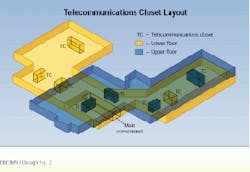
To make the best use of the 340,000-square-foot building, cabling system designers located telecommun-ications closets throughout the two-story structure. The main crossconnect is located on the first floor.

Each telecommunications closet contains seven cable-management racks. The two 23-inch racks on the left contain backbone and horizontal cable for voice applications. The third and sixth racks from the left support horizontal data applications. The fourth and fifth racks provide connectivity to the floor serving active equipment (Catalyst 5000s), which support the data applications. Rack seven provides connectivity for multimode optical-fiber cable and contains a power distribution device. Vertical cable management is provided between racks. Horizontal cable management is also provided behind and in front of each patch panel.
Robert Y. Faber, Jr., registered communications distribution designer (rcdd), is the manager of educational services at The Siemon Co. (Watertown, CT). For the past three years, he has developed and implemented a comprehensive training program for certified installers and end-users as part of the Siemon Cabling System. This is a standards-based telecommunications structured cabling system program that is based on industry-standard design principles and installation practices.

