Wiring a Category 5 110 block
Robert Y. Faber, Jr., RCDD, and Valerie Smith, EE, The Siemon Co.
Problem
Wiring 110 blocks has become difficult because of the Category 5 requirement--specified in Telecommunications Industry Association/Electronic Industries Association standard 568A--that pairs in unshielded twisted-pair cable be untwisted no more than 0.5 inch in the termination procedure.
Solution
The following procedure for terminating Category 5 UTP cable on a 110 connecting block will help ensure that the TIA standard is adhered to.
Procedure
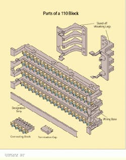
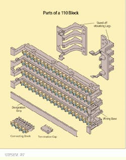
1) Mount the 110 wiring base on a properly prepared plywood wall surface, or attach it to a rack-mount bracket for use on a crossconnect frame or equipment rack. The area behind the bracket can be used for cable management and slack storage.
2) Route the cables into place through the openings in the wiring base.
3) Remove only as much cable jacket as necessary to terminate the conductors. Remember to leave some cable slack behind the wiring base or bracket for future reterminations.
4) Lace the cable conductors into the retention slots on the 110 wiring base. Be careful not to untwist the cable pairs more than 0.5 inch for Category 5 cables (and no more than 1.0 inch for Category 4 cables).
5) Inspect the cable pairs before terminating the wires.
6) Terminate the conductors using a five-pair automatic impact tool or equivalent. This action will seat 10 conductors at one time and cut off the excess wire.
7) Place a 110 connecting block on the head of the five-pair automatic impact tool. Align the connecting block over the appropriate 110 wiring base location and terminate the connecting block onto the base. The top of the connecting block is used for termination of the crossconnect jumper wire. A termination cap may be used on the top of the connecting block.
8) Label the connections on the 110 connecting base tabs, add-on designation strips or cover.
Robert Y. Faber, Jr., RCDD, is a corporate trainer, and Valerie Smith is an electrical engineer at The Siemon Co., Watertown, CT.
The 110 block can be attached directly to a wall or mounted using stand-off legs to provide space behind it for cable management.

