Shielded systems offer design alternative to UTP
Institutions that need a cost-effective, secure network that can handle higher bandwidth requirements than is possible with unshielded twisted-pair cable are turning to shielded media.
Steve Reed
Thomas & Betts Corp.
With today`s premises wiring, there are many existing and emerging applications that users want to implement in their organizations` networks: Token Ring, Ethernet, Asynchronous Transfer Mode (atm) 155, 100Base-T, desktop videoconferencing, and image transfer, to name just a few. For these and future applications, data speed and bandwidth requirements will continue to increase rapidly. In addition, data security and confidentiality are, and will continue to be, factors of growing importance for many companies and governmental facilities.
Traditionally, the design of a premises cabling plant incorporated unshielded twisted-pair (utp) cable for the horizontal cabling runs and, sometimes, the backbone cabling as well. This decision was made, in part, because utp costs less per drop than other cabling media. Also, wiring contractors are familiar with utp, and it is considered by many to be easier to install than other cables. Furthermore, it is often the case that unshielded copper cabling is "embedded"--that is, it has been used so extensively in the cabling plant that the building`s owner feels the existing plant is an investment worth preserving.
In fact, unshielded cable has been used so extensively in the United States that skepticism has developed about the use of other cabling media, such as shielded or screened cabling systems. However, if the true cost per drop is evaluated--in terms of the capability to use each link or channel to run multiple protocols--this other copper-based physical-layer option provides a number of advantages over utp, including greater transmission distances, electromagnetic compatibility features, a more secure future expansion and migration path, and overall system economy.
If we consider how quickly obsolescence occurs in this industry, planning a cabling system can be a gamble, both of company funds and one`s reputation. Shielded systems reduce the risk because they can handle higher bandwidth and also provide a more robust infrastructure than utp. Also, since shielded media can carry transmissions for greater distances than utp, the need for repeater equipment that may be necessary for a utp system can be eliminated, reducing the cost of the system over its lifetime.
Susceptibility to electromagnetic interference (emi) and radio-frequency interference (rfi) can be problems with utp systems, which depend on balancing two signals on a wire pair rather than shielding the medium to keep out noise. This problem is virtually eliminated in shielded systems.
These advantages of shielded cabling systems are proving to be so persuasive that several commercial, scientific, and industrial sectors--including financial institutions, health-care facilities, manufacturing complexes, and many Fortune 500 companies--are increasingly turning to shielded cabling for both new installations and retrofits.
Having decided to use a shielded solution, you should keep in mind several design and installation considerations. The first such consideration is what type of shielded system to use. Do you go with shielded twisted-pair (stp-a), screened twisted-pair (sctp), or individually shielded twisted-pair (istp) cable? And what is the difference between them?
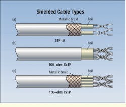
One choice is stp-a, which is commonly called the ibm cabling system. It consists of a 2-pair, 22-awg, 150-ohm cable with each pair individually foiled. The pairs are then wrapped with an overall braiding.
An enhanced data connector that is compliant with the 802.5 standard of the Institute of Electrical and Electronics Engineers (ieee--New York, NY) is also recognized in the ansi/tia/eia-568a commercial building cabling standard of the Telecommunications Industry Association (tia--Arlington, VA), and so could be used in premises cabling.
By designing a system using this type of cable and connector, you can give your customers bandwidth capabilities of up to 300 megahertz. However, stp-a can only be used for 2-pair protocols. This limitation leaves a question mark about the expansion capability of this system, because several of the networking protocols under development use all 4 pairs available in a standard utp cable. The Gigabit Ethernet Alliance, for instance, is working on a protocol that calls for 250-megabit-per-second transmission over all 4 pairs in a Category 5 utp cable.
Sctp, which is being installed more frequently today, is a 4-pair, 24-AWG, 100-ohm cable with an overall foil shield or foil-braid shield. This shielding provides protection against emi and rfi, yet it produces no drastic improvement in internal near-end crosstalk, attenuation, or attenuation-to-crosstalk ratio. Sctp, then, can be thought of as a Category 5 utp cable with an overall foil wrap. An alternative 22-awg cable may also be used, as long as it meets the transmission requirements for the category of cable being installed that are set forth in the tia building wiring standard.
The connector used in the sctp system is similar to those used in a utp design, with the exception that a tin-plated-brass metal plating or enclosure shields the connector. This design provides bandwidth capability of up to 100 MHz. Sctp is currently being reviewed by a task force, known as PN-3193, of the tia/eia-568a committee, preparatory to its acceptance as a standards-based wiring medium.
Manufacturers of yet another cabling system on the market claim it is an improvement over both stp-a and sctp systems. It is a 4-pair, 100-ohm istp cable, with each pair individually foiled inside an overall braid. The connectors used with this cabling design have only recently been developed and are proving to have bandwidth capabilities beyond the wiring standards as currently defined. Being a 4-pair system, istp provides the contractor and cable-plant manager with an option that permits multiple 2-pair protocols on one cable run--for example, two Ethernet, Token Ring, atm, video or any combination of these single media. In addition, istp allows for future expansion or migration to protocols that may require 4-pair implementation up to 300 MHz.
Uses of shielded cabling
Shielded cable, like other copper-based media, can be used in backbone applications as well as for horizontal cable runs. In an intrabuilding system, for instance, the shielding must be continuous from end to end. This means that only shielded system components--cable, connectors, patching systems, and patch and equipment cords--may be used, and the shield must be maintained at each interface--for example, at the interface between cable and connector. The intrabuilding cable also needs to be grounded at both ends and protected from ground loops and other electrical problems.
In an interbuilding system, the shield must be bonded at both ends to a building`s telecommunications grounding busbar (tgb). The ground potential in both cases--premises and campus--must not exceed one volt measured by the root-mean-square (rms) method.
For further information on grounding and bonding requirements, review the tia/eia-607 grounding and bonding standard, as well as local electrical codes, which may supersede even the National Electrical Code (NEC). (The NEC is available through the National Fire Protection Association, headquartered in Quincy, MA.)
When designing the horizontal cabling system in a new building, you should work closely with the electrical contractor to ensure that a proper tgb exists in every telecommunications closet. When retrofitting an existing building, it is prudent to ensure that there is a common ground in each closet, as well.
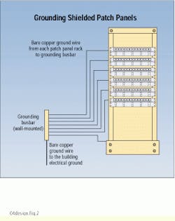
The closet should be designed so that for each patch panel installed, there will be a ground wire running to the tgb. For example, if you have six patch panels on a relay rack, you should have seven ground wires going to the tgb--six for the patch panels and one for the relay rack. The reason for this redundancy is that, should a ground wire become disconnected from the tgb and a horizontal cable become energized, the terminals affected will be localized to one particular panel, saving all of the other panels on the relay rack.
Otherwise, overall design considerations for a shielded or screened cabling system are the same as they are for a utp system. For instance, all cable runs are to be home run from the work area outlet to the closet, using a maximum link length of 90 meters. As is the case in the backbone, you must make sure that the ground potential is no more than 1V rms. There should also be no more than 3.5 ohms of impedance between the green wire at the nearest electrical outlet and the cable shield. If any higher voltage or resistance is encountered, a problem exists that should be rectified before using that cable link.
The work-area outlet must have a jack that is designed for use in either stp-a, sctp, or istp systems. Sctp systems generally use the same faceplate as is used in utp installations. A special faceplate designed for the data connector will be needed with stp-a systems. You must also use a screened or shielded patch cord as an interface from the wallplate to the data terminal.
The secret to a correctly installed shielded system lies in the grounding and bonding. Properly designed and installed, the shield will be continuous from end to end, with no degradation of transmission performance. This gives your customer a robust cabling infrastructure today that allows for expansion in the future.
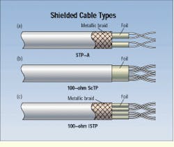
The stp-a shielded cabling configuration consists of two individually foiled wire pairs wrapped in an overall braid (a). The 100-ohm ScTP configuration consists of 4 wire pairs surrounded by an overall foil shield or foil-braid shield (b). The istp configuration boasts 4 individually foiled pairs enclosed in an overall braid (c).
Proper grounding procedure for a shielded relay rack calls for individual grounding of each patch panel, as well as grounding of the rack itself, to the telecommunications grounding busbar.
Steve Reed, an 18-year veteran of the telecommunications industry, is currently technical services manager of the Premises Wire Management Group at Thomas & Betts Corp. (Memphis, TN).


