10GBase-T first draft imminent; SNR issues a main focus
Formed last November, the IEEE 10GBase-T task force 802.3an is scheduled to deliver the first draft (D1.0) of the standard in July at the IEEE plenary meeting. After more than a year of debate on the rationale and the technical basis for establishing the project, the IEEE 10GBase-T task group has targeted July 2006 for the standard approval.
10GBase-T objectives, operation
The 10GBase-T standard will extend the Ethernet family of twisted-pair physical layer specifications to a data rate of 10 Gbits/sec—a factor-of-10 increase over 1000Base-T. The standard's objectives establish the basis for judging the project's success or failure, and provide the necessary roadmap for the development of technical specifications. The objectives provide both the design goals and constraints.
The primary 10GBase-T cabling-related objectives are to provide a standard that:
- Enables 10-Gbits/sec data transmission over Class E and Class F ISO/IEC 11801 cabling (At least 100 meters on four-pair Class F balanced copper cabling; At least 55 meters to 100 meters on four-pair Class E balanced copper cabling);
- Supports a bit error rate (BER) of 10-12;
- Meets CISPR/FCC Class A electromagnetic compatibility (EMC) limits.
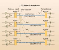
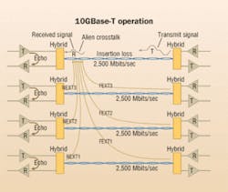
The topology for 10GBase-T will be very similar to 1000Base-T. Each of the four pairs is a full duplex channel, supporting an effective data rate of 2,500 Mbits/sec simultaneously in both directions, achieving an aggregate data rate of 10,000 Mbits/sec (10 Gbits/sec).
Design challenges. The primary challenges to transmitting 2,500 Mbits/sec on twisted-pair are the limits imposed on the transmitter power (transmit signal) and transmit-signal spectra to meet the CISPR/FCC Class A electromagnetic compatibility (EMC) objective, and the channel bandwidth limits imposed by the cabling impairments (noise). The optimal implementation manages to use the available channel bandwidth as efficiently as possible to maximize the available power at the receiver, and minimize the cabling impairments through cancellation.
10GBase-T noise environment. The figure "10Gbase-T operation" (above) illustrates the transmission of 2,500 Mbits/sec on each of the four wire pairs. The transmit signal is impaired by the cable insertion loss. The noise from three near-end crosstalk (NEXT) disturbers, three far-end crosstalk (FEXT) disturbers, and the echo combine with the receive signal. Using advanced signal-processing methods, the receiver extracts the signal from the crosstalk and echo noise. In addition to internal cable impairments, alien crosstalk noise can couple in from adjacent cables.
Signal-to-noise (SNR) and line coding. The signal-to-noise ratio (SNR) at the receiver is the most important figure of merit for a communication channel. The probability of error is mathematically related to the SNR and the line code used. Line coding is the process of converting the discrete bits into signals suitable for transmission over the communication channel. The conversion of bits into codes (encoding) and the transformation of the encoded data into symbols increase the data transmission's bandwidth efficiency.
The symbols are the representations of the encoded bits as voltages on the pairs. For binary transmission, where two symbols are used (e.g., 1 and 0), the number of symbols per second (the signaling rate in baud) is equivalent to the data rate in bits per second. For multi-level signaling, the relationship between signaling rate in baud and data rate is dependent on the number of the symbols' voltage levels. As an example, if four voltage levels are used as symbols, each voltage level can represent two binary digits (bits of data); therefore, the data rate in bits-per-second is twice the signaling rate in baud (two bits of data for every baud). In this example, the signaling rate in baud is one-half of the data rate, resulting in a reduction in the signal bandwidth.
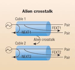
SNR for 10GBase-T. 10GBase-T will incorporate advanced digital signal processing (DSP) techniques to perform crosstalk cancellation between the pairs in the cable as well as echo cancellation on each pair. While eliminating the internal cable impairments through DSP greatly expands the cabling channels' usable bandwidth, the noise coupled between cables—referred to as "alien crosstalk"—is not easily cancelled. (See figure, "Alien crosstalk," above) For 10GBase-T, alien crosstalk is the dominant noise source and, therefore, the SNR at the receiver is the ratio of the signal (insertion loss) to alien crosstalk noise appearing at the receiver. The SNR in conjunction with the line code determine the probability of error (BER).
10GBase-T cabling
Based on their investigation to date, the P802.3an task group has adopted the Class E channel limits extrapolated to an upper frequency of 625 MHz as a starting point for the 10GBase-T cabling specifications. The Class E channel parameters used in the 10GBase-T specification are insertion loss, return loss, pair-to-pair NEXT, power-sum NEXT, and pair-to-pair equal-level FEXT (ELFEXT). The ISO/IEC 11801 Class E cabling channel specifications are nearly the same as the ANSI/TIA/EIA-568-B.2-1 Category 6 cabling channel specification.
The Class F channel limits exceed the performance requirements of Class E (adopted as the 10GBase-T cabling specifications), therefore, Class F specifications are referenced only where applicable to requirements specific to Class F, such as power-sum alien NEXT (PS ANEXT).
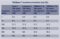
10GBase-T insertion loss. To address the objective of supporting operation over at least 55 to 100 meters on four-pair Class E balanced cabling, the insertion loss of both 55 and 100 meters of Class E are specified. (See table, "Class E maximum insertion loss (100 and 55 meters)," right.)
10GBase-T Class E maximum insertion loss (100 meters). The results of extrapolating the Class E insertion loss equation to the extended frequency are provided in the table, "10GBase-T maximum insertion loss."
Alien crosstalk specifications
Alien crosstalk is not adequately specified in the ISO/IEC 11801 or TIA cabling standards. Lacking a cabling standard reference for alien crosstalk specifications, the 10GBase-T task force established alien NEXT (ANEXT) limits based on ANEXT measurements submitted to the task force. The cabling measurements were submitted to the task group as representative of a "reasonable" worst case.
For Class E UTP, the 55-meter limit was established based on alien crosstalk measurements between a cable and six adjacent cables in a six-around-one configuration, where the disturbed cable is the central cable and adjacent to all of the other cables with tie wraps every 2.5 feet. In addition, the measurements were taken with the seven cables placed in a conduit with a fill capacity of 40%. The configurations were designed to control the cable adjacency and to be consistent with cabling installation practices. In the conduit configuration, the cables are not tie-wrapped and are allowed to move freely during the cable pull. The measurement configurations included the connecting hardware. 10GBase-T operation is designed to operate over at least 55 meters of installed Class E UTP cabling with a "reasonable" worst-case alien crosstalk environment.
PS ANEXT to SNR
The cabling requirements of echo, NEXT, and FEXT within a cable are expected to be reduced to a small residual noise by using cancellation methods. Given that the impairments within the cable have been accounted for through cancellation, the 10GBase-T SNR is primarily based on the ratio of the signal (insertion loss) to alien crosstalk noise appearing at the receiver.
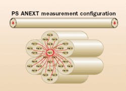
PS ANEXT loss is determined by summing the power of the individual pair-to-pair NEXT disturbers between the adjacent cable pairs. (See figure, "PS ANEXT measurement configuration," page 19.)
The Class E UTP 55-meter length limitation is based on the assumption that the channel exhibits the maximum insertion loss and the worst-case alien crosstalk. Even under the worst-case alien crosstalk conditions, lengths of Class E UTP greater than 55 meters can be supported if the "measured" channel insertion loss is less than the maximum allowed insertion loss for 55 meters. Insertion loss measurements of "real" installed cabling typically exhibit margin from the maximum, and longer distances can be supported. The distance limitation is based on the "measured" channel insertion loss, not on the physical length.
The PS ANEXT limits provided are derived from the channel's insertion loss and the required minimum receiver SNR.
For a 100-meter Class E channel with a maximum Class E insertion loss, the PS ANEXT loss between pairs in a cable (disturbed pair) and pairs in adjacent cables (disturbing pairs) shall be greater than:
{62 - 10*log10(fMHz/100) 1 MHz<=f<=100 MHz} {62 - 15*log10(fMHz/100) 100 MHzFor a 55-meter Class E channel, with a maximum insertion loss of Class E scaled to 55 meters, the PS ANEXT loss between pairs in a cable (disturbed pair) and pairs in adjacent cables (disturbing pairs) shall be greater than:
{47 - 10*log10(fMHz/100) 1MHz<=f<=100 MHz} {47 - 15*log10(fMHz/100) 100 MHzFor a 100-meter Class F channel, with a maximum insertion loss of a Class F channel of 100 meters, the PS ANEXT loss between pairs in a cable (disturbed pair) and pairs in adjacent cables (disturbing pairs) shall be greater than:
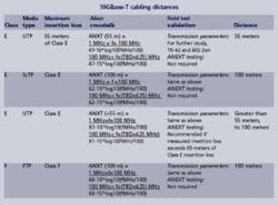
{60 - 10*log10(fMHz/100) 1 MHz<=f<=100 MHz} {60 - 15*log10(fMHz/100) 100 MHzThe 10GBase-T cabling distances supported are dependent on the cabling's insertion loss and alien crosstalk performance. (See table, "10GBase-T cabling distances," above.) For Class E cable constructed with a foil screen (FTP) and Class F, the measured alien crosstalk performance is better than the 10GBase-T alien crosstalk requirements and, therefore, lengths of 100 meters can be supported. FTP is referred to as screened twisted-pair (ScTP) in TIA/EIA-568B.1. For Class E UTP, the 55-meter limit was established based on alien crosstalk measurements of installed UTP cabling representative of a "reasonable" worst case.
The results of alien crosstalk measurements of Class E FTP and Class F cabling have exceeded the 10GBase-T alien crosstalk requirements and, therefore, need not be validated in the field.
The field testing of installed cabling for 10GBase-T operation is under study in TIA-TR-42, the TIA Engineering Committee on User Premises Telecommunications Infrastructure, in cooperation with the 802.3an task force.
Two new projects
The TR-42 project, designated PN-3-0134, is to investigate the balanced cabling performance (up to 625 MHz) for both Category 6 and Category 5e cabling for 10GBase-T applications. Applicable Category 6 data and guidelines from the study will be presented in a new Telecommunications Systems Bulletin, TSB-155. Category 5e and Category 6 measurement data will be shared directly with IEEE 802.3.
The PN-3-0134 project consists of a study of measurements of Category 5e and Category 6 cabling transmission performance and alien crosstalk, including the relationship of transmission parameters and alien crosstalk with their field testing and mitigation. Category 5e and Category 6 measurement data will be shared directly with the IEEE 802.3 10GBase-T task force as it becomes available.
Lengths of Class E UTP greater than 55 meters with maximum insertion loss may be supported if the alien crosstalk is mitigated. Alien crosstalk occurs in both cables and connector components. In general, alien crosstalk is reduced as the distance between adjacent cables and connectors increases.
From an application perspective, due to the wide bandwidth of 10GBase-T signals, the main concern is the alien crosstalk noise from other 10GBase-T links. The relative contribution from other sources, such as 1000Base-T, is very small but may become significant if the disturbed 10GBase-T pair has a maximum insertion loss. In addition, increasing the length of separated patch cords will reduce the coupling voltage and reduce the coupled noise that appears back at the receiver.
Possible field-mitigation strategies include:
- The separation of cables and patch cords to reduce the amount of coupling between adjacent four-pair cables;
- The separation of 10GBase-T ports on the patch panel;
- Limiting the number of 10GBase-T channels in bundled cable and conduit;
- The replacement of connectors or patch panels.
The TR-42 project, designated "SP-3 4426: Augmented Category 6 Cabling," is to develop cabling and component specifications plus test procedures to support the operation of IEEE 802.3 10GBase-T over 100 meters of structured balanced twisted-pair copper cabling. This project includes extending the frequency range and adding requirements to those specified in TIA/EIA-568B.2-1. The resulting requirements will be presented in a new revision or addendum to the TIA/EIA-568-B standard.
Chris DiMinico is president of MC Communications, a telecommunications consulting firm. Larry Cohen is a senior scientist at SolarFlare Communications (www.solarflare.com), a company developing integrated solution for the 10GBase-T PHY.
