Where does optical return loss matter?
By Ashley Massey, Corning Optical Communications
The Institute of Electrical and Electronics Engineers (IEEE) recently released new specifications within IEEE 802.3 for 200G and 400G Ethernet transmission. Within those specifications are parameters that define the optical pathway requirements to support these various data rates including channel insertion loss (IL) and optical return loss (ORL) for the link along with discrete reflectance values for single optical components such as connector pairs within that link. Defining these parameters is not new for IEEE, but the way it is now being defined may appear slightly more complex than previous lower data rates, which has led to some confusion within the market.
The purpose of this article is to lay out a basic definition for these parameters and explain the IEEE 802.3 optical requirements to support these rates. Additionally, it will explore how these parameters should be used during both the design and construction phases when building these optical networks.
Building the ORL story
Within a fiber-optic channel or pathway, there are several components a signal will have to travel through. The fiber itself has intrinsic loss (due to Rayleigh scattering) as do connectors, splices, and other events within a system (due to Fresnel reflectance). Reflectance (also stated as return loss or back reflectance) is the ratio of reflected power to incident power at a connector junction or other component. It is measured in decibels (dB) and stated as a negative value. Reflectance is caused when the optical signal travels between materials with different refractive indexes, typically from fiber to air and back to fiber. An air gap can be due to dirt, debris, enface geometry or other causes, and will impact the strength of that reflection. This is important because high reflective events can return to the source with sufficient power to impair or damage sensitive electronics.
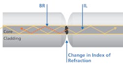
Optical return loss (ORL) is defined as the amount of light reflected back to the optical source an dis expressed as a ratio of the power of the outgoing signal to the power of the reflected signal. Measured in dB and stated as a positive value, it is component reflectance combined with cumulative backscatter of the fiber in a system, network channel, or link. The insertion loss (IL) is the signal that is lost into the cladding. The primary cause for reflectance is a change in the index of refraction (IOR). The change in IOR is due to the signal traveling from fiber to air and back into fiber.
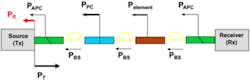
The figure shows a simulated network and a representation of how each component contributes to the ORL. As components move farther from the source, they will have less impact on ORL. This is due to their reflectance needing to travel back through the fiber, connectors, and any additional components before arriving at the source. As such, some reflectance will degrade and be lost due to attenuation. Thus, impact is based on distance from the transmitter as well as the reflectance at any single component.
Where does ORL matter?
IEEE 802.3 is a collection of Ethernet standards that continue to define migration paths to higher data rates. As network demands within data centers have increased, the attention to ORL has escalated. Standards have created more stringent requirements for ORL for these higher data rates (exceeding 100G).
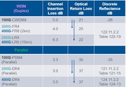
Unlike channel loss, formulating the ORL for a link is a complex formula. Thus, the standards have provided tables that contain a range of reflectance values based on the number of components within a channel. In turn, the number of components dictates the minimum reflectance value necessary to achieve the ORL required for the link. Designers can use these tables to plan their network.
For parallel 400G-DR4, the standard utilizes Table 124-13 to represent the discrete reflectance allowable for each mated pair and is dependent upon the number of mated pairs in the link. For example, if a mated connector pair is specified at -47 dB reflectance, a total of 6 mated pairs each at -47 dB can be designed into the link. If each is specified at -49 dB, then a total of 10 mated pairs can be designed into the link, solely based on reflectance. The total channel loss must also be taken into consideration when designing the links. Similar tables are presented in the WDM standards for 200G and 400G, and can be used to aid designers in the allowable number of mated pairs in structured cabling links.
Additional standards and other specifications
All fiber-optic components must perform to specifications. TIA-568 is a structured cabling standard, of which components are a part. It defines various specifications for mated connector pairs within a link including reflectance and insertion loss. GR-326 is a component standard that serves a slightly different purpose, focusing on singlemode connectors and jumpers. The table depicts the reflectance or return loss specification from GR-326, TIA-568.3-D, and Corning’s own standard performance for typical connector styles deployed in a data center. As the table indicates, Corning’s products (MTP and LC connectors) exceed industry specifications across all connector endfaces.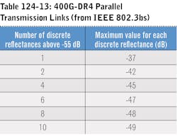
Singlemode MTP/MPO connectors are APC and thus, backbones that have deployed MTP connectivity can easily manage the improved reflectance and ORL specifications. For link that use LC connectivity, the UPC specification requires a closer look. UPC connectivity will have a greater impact on the ORL than the APC connectivity because of the higher reflectance from UPC endface.
Referring back to Table 124-13 from IEEE 802.3, note that up to 10 mated pairs are permitted in the link provided each mated pair is at least -49 dB. Using Corning singlemode MTP connectors, which will always be APC, the reflectance well exceeds the limit for the maximum number of pairs permitted in the link. Therefore, the insertion loss will become the defining characteristic in determining the number of mated pairs allowed in the link. If LC UPC connectivity is used and the connectors solely comply with GR-326 (-40 dB), their performance will be such that only 1 connector pair can confidently be designed into the system at -37 dB. However, using products with the performance of Corning’s LC UPC products, -55 dB exceeds the -49 dB allowance for up to 10 connector pairs. Therefore, APC connectivity is not required for high-speed Ethernet applications based on the ORL requirements.
Need to test?
As noted above, it is difficult for a designer to predict ORL for an entire system based on component reflectance. The tables for individual component reflectance are used to ensure ORL requirements are met. Testing for ORL is not required because the standards provide reflectance values for the components that ensure the link meets ORL. Additionally, our own reflectance specifications at Corning exceed the requirements laid out in the standards. However, if you choose to test for ORL, pass/fail criteria should be obtained from the specifications of the active components that will be used in the network. This is usually listed as “reflectance tolerance” of a transceiver. If this information is not available at the time of testing, refer to the IEEE standards.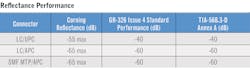
There has been a change in the requirements for reflectance and ORL for higher data rate systems (≥200G). This has generated some concern and confusion in the market. Due to the quality of connectors Corning manufactures, there is no need for concern among users of these connectors. Corning singlemode MTP connectors are always APC, and thus, will not limit the number of connectors in a link based on reflectance and ORL. Corning’s LC UPC connectors exceed the current requirements for up to 10 pairs in a single link. While Corning’s LC APC connectors always exceed these requirements, it is not necessary to make that switch to ensure compliance with these requirements. It should also be noted that ORL better than -37 dB is not required for network designs covered by IEEE 802.3-2018.
Ashley Massey is systems design engineer II with Corning Optical Communications.

