Rearchitecting central offices into data centers
By Robert Reid, Panduit and John Shuman, Prysmian Group
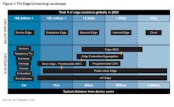
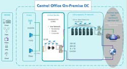
Telecom carriers understand they must continually modernize their networks to remain, or become, industry leaders. Over the past decade, revenues have stagnated, and traffic demands have increased exponentially, exacerbated by people working at home during the COVID-19 pandemic. This pressure has accelerated the adoption of central office rearchitected as a data center (CORD) technology in telco central offices (COs). For many of them, transforming their COs into data centers is an opportunity to tap new business potential. By reconfiguring their existing COs into low-latency edge computing “cloudlets” and colocation multi-tenant data centers (MTDCs), CORD initiatives strive to replace yesterday’s purpose-built hardware with more-agile, software-based elements and, in doing so, ensure that legacy carrier COs become an integral part of a larger cloud strategy, enabling resilient, low-latency network services to customers.
The “last mile” is an arena of intense competition, with hyperscale and colocation providers leading the way. To respond to these challenges, carriers must understand how to turn the central office into a modern data center, with modern equipment, which is easily configurable, upgradeable, and agile.As edge networks become directly connected to cloud, bringing cloud economics into the central office through software defined networks (SDN) and network function virtualization (NFV) will be critical to the operators’ ongoing success.
This article will cover an introduction to CORD—its value proposition, applications, benefits, required technology, and physical differences between a standard CO and one that’s been changed over to a data center.
The value proposition of CORD
Transforming the traditional CO into a modern data center allows operators to bring in new revenue streams by offering new services, such as multi-tenant leased space, metro services and cloud connectivity, essentially mimicking what colocation data centers have done for the past two decades.
However, in addition to productivity gains, the incentives for carriers to modernize are clear and tangible. The cost of maintaining public switched telephone networks (PTSN) versus IP networks is considerable from the perspectives of capital, operational, and facilities costs; additionally, telecom equipment is slow to evolve and difficult to upgrade.
Many COs have not hanged much over the past 40 to 50 years. They typically have up to 300 different types of equipment, which is a huge source of operational expense (opex) and capital expense (capex). Bringing cloud economics into the CO through SDN and NFV will cut costs and increase revenue streams, but will require significant infrastructure transformation.Moving from a copper-based central office to a fiber-based central office also enables operators to shrink the footprint for both the equipment and the physical plant, which frees up space to add more server and storage racks, and potentially some customer space and/or customer racks.
The top challenges when converting a conventional CO into a next-generation CO/CORD deployment are security, power and bandwidth monitoring, and cabling infrastructure. In each of these areas, the CO operator must implement changes as they move forward to effectively run a MTDC.
It’s important to keep in mind that IP network cabling requires adherence to a different set of standards (TIA rather than WECO) when converting the CO to a CORD.
Security
In a traditional CO, security is relatively simple because only one company has access to the building, and it’s tightly controlled. A CORD deployment must accommodate multiple clients who will need access to the CO’s data center to work on their equipment. Typically MTDCs use six layers of security.
- Layer one is the outside perimeter, which usually is made up of fencing around the whole property, with cameras and an entry gate.
- Layer two is the outside common space, which monitors the parking lot and common space around the outside of the building using cameras and sensors.
- Layer three is the security/reception area. This area is where tenants check in, provide a photo ID, have their identity confirmed and receive a badge.
- Layer four is the man trap, an area where entry/exit is slowed by doors that open one at a time.
- Layer five is the data center room door, which allows access into the data center room. It usually has card and/or biometric access control.
- Layer six is the locked door on the data center cabinet, which prevents unrestricted access to the equipment in the cabinet.
Power monitoring
In traditional COs, power monitoring occurs at the entrance of the building or at the DC power distribution. They are limited to their own DC power through battery distribution fuse bays and battery distribution circuit breakers.
Colo facilities require the data center operator to monitor power with a higher level of granularity, to ensure that the level of power being used is what they have agreed to deliver to the end customer. Typically, power is monitored at the customer attachment level, which could be the cabinet, or the feed to a cage. In addition, power will change to mostly AC, using uninterruptible power supplies (UPSs) that incorporate battery plants with associated switch gear panels and circuit breakers.
Bandwidth monitoring
Bandwidth monitoring is not a new concept for CO operators, but again will need to be adjusted so that more detail is available. In a traditional CO, bandwidth is monitored down to a room or distribution switch level. In a next-gen CO/MTDC, bandwidth needs to be monitored down to an access switch port level to accurate bill tenants for how much bandwidth they are using or pushing onto the network. Ninety-five percent bandwidth measurements are the industry standard for measuring bandwidth within data centers.
With each of these areas, the upgrade in service comes with additional revenue streams.
Transitioning legacy telco equipment
Because CORD is designed to serve low-latency needs, COs will need to transition to more data center-like facilities. The evolution of network architecture will lead to a reduction of 30 to 50% in the amount of space used in current COs and the new CO infrastructure will be more data center and enterprise-like.
Both active and passive components will be impacted by the new CORD architecture, including requirements for new cables, connectors, and accessories. Network management cost reductions and increases in performance are the key drivers of the transition from traditional telco equipment to data center-like equipment, which includes racks and cabinets, cooling infrastructure, power infrastructure, fire suppression, and grounding and bonding.
Cooling
COs originally were designed with minimal cooling due to the high tolerance of the telecommunications equipment in them. As traditional telco equipment is replaced by common servers, the method of cooling needs to follow data center standards. In a CORD environment, data center cooling methods like chilled water and refrigerant cooling systems are going to be necessary to address high heat load situations using lower temperatures. Strategically placed cooling equipment, such as chillers or computer room air conditioning (CRAC) or computer room air handler (CRAH) units will need to be added and operators will need to figure out refrigerant systems.
Power infrastructure
The power infrastructure also needs to change as COs are turned into data centers. COs were originally designed using 48 V DC power backed by a battery plant that could support more than 48 hours without utility power.
To achieve the performance required, a CORD conversion will require a shift to the use of AC power, which is the predominant source required to power data center equipment, backed by a battery plant and generator that could support more than 48 hours without utility power.
CORD deployments will handle various mission-critical applications that are sensitive to latency. Loss of power, even for a few seconds, can cause massive losses, so next-gen COs must provide a reliable, uninterruptible power supply to prevent downtimes that risk disrupting operations. This will require operators to add UPS with battery backups (to provide short-term power to bridge the gap between the loss of utility power and activation of generator power), which will need to be monitored. In addition, next-gen COs typically will use data center power distribution units (DCDU), large industrial power distribution units (PDU), to take power from the UPS and transform the power from 480 volts AC to either 400 volts AC for newer data centers, or 208 volts AC for older ones.
Remote power panels (RPP) are the circuit breaker panels used in data centers to provide the flexibility to cut or restore power to individual circuits and mitigate damaging surges, and cabinet power distribution units (CPDU) are used to distribute the power to IT equipment within each cabinet. During typical operation, each CPDU carries no more than 50% of the IT load to provide redundancy (A + B feeds), in case of distribution equipment failure.
Fire suppression
Traditional telco fire suppression does not meet the dense coverage needs of more modern data centers. Data centers typically use more than just water for the fire suppression, such as a dry charged system with sprinklers, dual stage, with a denser emitter layout.
Hybrid systems may also use gas-type chemicals like Halon of FM2000 as well as dielectric fluids that are emitted under high pressure as a fine mist rather than a spray like water-based systems.
Optimizing the cabling infrastructure
Cabling is critical to a data center’s performance. There are a number of ways to optimize CO cabling infrastructure as well as potential problems to be aware of. Whether it’s an inappropriate cable type for the application, reversed polarity, or poor physical installation and cable management/protection, a poorly implemented cabling infrastructure can impact cooling, can be a source of increased downtime, and can affect the long-term viability of the data center cable plant. More information on the minimum requirements for the telecommunications infrastructure of data centers can be found in the ANSI/TIA-942-B standard.
Designers of COs should consider the highest available grade of copper or fiber (singlemode and multimode) cables to meet today’s applications and those of the future. The economics of using older cabling may be alluring, but could result in increased installation time and long-term reliability issues because some older fiber cables won’t tolerate the reduced bend radii required in today’s CO. In general, next-gen COs are moving away from copper for higher-speed channels in favor of optical fiber, as copper simply cannot support high data rates at the required reach. AT all levels of the network, the new generation of leaf/spine fabrics and high-speed server interfaces are putting an increased demand on the physical layer of today’s networks.
Let’s look at the areas that require upgraded cabling infrastructure.
Meet-me room (MMR)/Entrance facility
Traditional colocation data centers with carrier hotels use the meet-me room (MMR) to control and manage connections for customer-to-customer and telco providers-to-customer in the data center. The customers can be cage or private rack customers that will have a connection from their space to the MMR where the colocation data center operator manages the requested connection.
Telco providers also have connections to the MMR to provide transit connections. Typically, singlemode fiber is used in the MMR with crossconnects installed to provide service customer cages or a private rack.
Data center
Central offices are becoming the landing spot for what can be called a kernel of the cloud. As operators migrate from a traditional CO to a CORD deployment, connectivity will be changing away from copper and more toward active optical solutions and traditional fiber structured cabling to keep up with data rates.Cloud and edge data centers have been upgrading fabric serial lane rates to 400 Gbits/sec (from 2019 onward) and evaluating very short reach (VR) lower-cost, multimode-fiber-based (<100 meters) solutions for some of the multimode switch interfaces.
Category cabling, direct attach copper (DAC) cabling and active optical cabling (AOC) currently present the lowest-cost “fixed” option for switch-to-server interconnect at current server network interface card (NIC) lane rates (at 10 or 25 Gbits/sec). These will move toward 50G NICs, and eventually 100G, as 400G multimode fiber VR SR8 optics are mainstreamed as low-cost options versus DR4 for short reach.
Copper cable
TIA and ISO standards group cables and connecting hardware are broken into different performance categories. These standards specify intrinsic bandwidth and data rate capability for each category.These specifications include electrical performance parameters and are tested within a specific electrical frequency range or bandwidth.
Application reach
Several types of copper cabling are currently used in COs, including DAC cables, which have factory-terminated transceiver connectors on each end. DAC cables are used to connect network equipment—generally switches, routers and other network equipment, as well as to connect servers to switches or storage equipment. DAC cables are constructed from shielded copper cable that generally ranges from 24 to 30 AWG. They are typically used with ToR connections, but as COs approach 50G, operators will need to move away from DACs, which can support only 5 meters or less at 25G, to AOCs.Fiber access a key point
Fiber cabling systems deployed today should be selected to support future data rate applications, such as 100G/400G Ethernet and Fibre Channel greater than or equal to 32G.
Several recognized horizontal fiber cabling media solutions are applicable to CORD implementations.
- 850-nm laser-optimized 50/125-micron multimode fiber cable OM3 or OM4 (ANSI/TIA-568.3-D), with OM4 recommended; OM5 fiber solutions to support 40G and 100G shortwave wavelength division multiplexing (SWDM) applications. These fibers provide the high performance as well as the extended reach often required for structured cabling installations in data centers.
- Singlemode optical fiber cable (ANSI/TIA-568.3-D)
COs are driven by the ever-increasing need for speed that generates a capacity crunch. As a result, fiber counts in the COs are increasing exponentially. Whereas trunks used to typically contain 72 or 144 fibers, they are now reaching 288 fibers and higher.
Cabling to support pod-based leaf-spine architecture
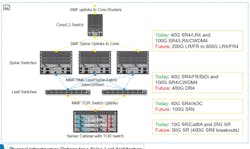
With the change from hierarchical star to leaf-spine architectures, the copper and fiber cabling infrastructure has changed, based on the transition from ToR to EoR or MoR leaf-spine deployments. With switches capable of higher throughput and Radix (the product of lane rate and data rate) count, a single switch can manage many more servers. This means that CO operators may choose to move from a 1:1 ToR switch-to-rack configuration to a more-cost-effective MoR or EoR mode with chassis-based high Radix switches.In one design scenario, leaf switches are placed in MoR/EoR cabinets and connected to ToR access switches (or directly to servers for smaller deployments) across an entire row using SR4 transceivers/multimode cabling or AOCs. Both MoR and EoR deployments may require cabling distances of 15 to 30 meters to reach ToR switches (or servers) in the row and as such, category cabling is not practical for data rates above 10G.
Spine switches are collapsed into a remote intermediate distribution frame (IDF) row and can be interconnected to leaf switches with multimode SR4 optics or longer-reach singlemode optics such as DR4.
Typical hardware for MTDC CORD will be a collection of customer/OEM-specific servers and storage, interconnected by a leaf-spine fabric of customer/OEM-specific switches. Many third-party systems integrators build complete install-ready (with software) server pods in “rack-and-roll” configurations to the tenant’s own specifications, although some tenants might establish their own L-S fabric, with discrete switching server cabinets, for connection to the CO network.
SR8 enables transition
While today most switch ports are at 100 Gbits/sec or below, the expectation is that by 2025, more than 60% of switch ports will be 100 Gbits/sec or higher. This growth in switch-port speed is also met by higher uplink speeds from the server to the network. Server connection speeds are also transition from 1 or 10 Gbits/sec to 25 Gbits/sec and above. While in most data centers today the connectivity between the server and the switch is at 1G or 10G, the expectation is that by 2025, 60% of the ports facing the switch will be at speeds above 10G, with 25G making up close to 30% of interconnection speeds.
To address higher bandwidth requirements, the switch silicon must scale either through an increase in switch Radix or lane bandwidth. Over the past nine years, switch Radix has increased from 64x10G to 128x25G, now to 256x50G, and soon to 256x100G.Server attachment rates can be selected by grouping a number of SR8 ports together as required with structured cabling and this cabling becomes migratable as lane rates increase. The industry is evolving toward 256 lanes at 100G, primarily because it saves space. These lanes can be collapsed into a chassis-based switch, and centralized either at the EoR, the MoR, or somewhere else in the data center, away from the servers.
400G SR8 technology is a compelling solution for switch-to-server interconnect because it can be used in 8-way “breakout mode” to support 50G server NICs from a single SR8 400G switch port, and in the future to 100G/200G from a SR8 800G/1.6T switch port.
There is no doubt that in the race to support the “last mile,” CO operators are well positioned to move into this lucrative opportunity. By repurposing existing central office space into data centers that can support new applications and services, telecom companies can turn around flagging revenues, reuse existing facilities, and become competitive in this emerging environment. It’s no wonder that, according to IHS Markit, among the largest global service providers, at least 70% are moving forward with plans to deploy CORD.
Robert Reid is senior technology manager for Panduit’s data center connectivity group. He defines product development direction for Panduit’s fiber-optic structured cabling product line.
John Shuman is global product manager for telecom and data center at Prysmian Group. He has 25 years’ experience in data center design and construction, telecom networks, and passive optical distribution component design.


