Deploying multimode fiber connectivity in the data center
Careful product, technology, and architecture choices can enable low-loss performance in high-data-rate applications.
by Alan Ugolini
When selecting an optical-fiber cabling solution for the data center, it makes strategic and economical sense to choose one that will maximize lifecycle and reduce capital and operational expense. An optical-cable infrastructure that can be fully utilized for 15 to 20 years will more than likely have to be operational through multiple generations of system equipment and at least two generations of data-rate increases.
Consideration of solution specifications, such as cabled fiber skew rate, optical-fiber bandwidth, connector-termination interface, modal noise, and connectivity performance, play an important role in realizing long lifecycles for the optical-cable infrastructure.Another attribute that is gaining importance in guaranteeing longevity of the optical physical layer in the data center is the channel insertion loss.
The Telecommunications Infrastructure Standard for Data Center TIA-942 defines a channel as the end-to-end transmission path between two points at which application-specific equipment is connected. The performance of optical networks depends on the ability of each channel to meet bit error rate (BER)requirements as specified in the respective transmission standard.
Maximum multimode fiber channel distances are defined in the particular standard, which is linked to a specific fiber-bandwidth performance specification and channel insertion loss budget. For example, the channel insertion loss budget for a 300-meter 10GBase-SR link using OM3 fiber at 850 nanometers (nm) is 2.6 dB. Of this 2.6 dB budget, 1.1 dB is allocated to the intrinsicfiber loss itself. Fiber splices and/or connector lossestake up the remaining 1.5 dB of the budget.
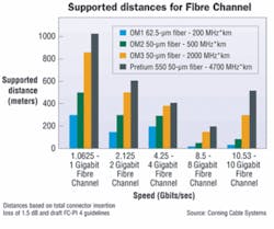
Channel insertion loss budgets for higher data rates are restrictive compared to historical, lower-speed variants. Additionally, with every increase in data rate, the supporting multimode fiber end-to-end distances have decreased. This trend of restrictive channel insertion loss and decreased supported channel distances should be noted when deploying a structured optical cabling network in combination with modular high-density MPO cabling solutions.
Going structured for flexibility
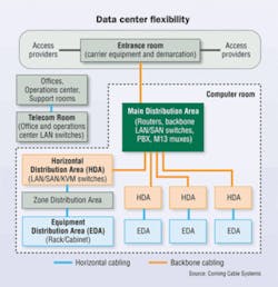
Implementing a structured cabling system in the data center is important to maximize the efficiency and lifecycle of thecabling infrastructure. A structured cabling solution, as recommended in the TIA-942 standard, optimizes the cabling plant’s flexibility to meet current and future networking require-ments by facilitating moves, adds and changes (MACs).
The data center main distribution area (MDA) includes the main crossconnect (MC), which is the central point of distribution for the data center structured cabling system. Backbone cabling is star-networked from the MC throughout the data center and, in particular, to horizontal distribution areas (HDA). Likewise, horizontal cabling is installed in a star top-ology from the horizontal crossconnect in the HDA to each equipment distribution area (EDA) or, alternatively, to a zone distribution area (ZDA) located between the HDA and EDA.
A horizontal crossconnect is not mandatory. For example, data centers using optical fiber may implement data networks with centralized electronics rather then distributed electronics. Centralized optical-fiber cabling is designed as an alternative to the optical crossconnect located in the HDA in the support of centralized electronics. Centralized optical cabling provides connections from the data center’s EDA to the centralized crossconnect by allowing the use of pull-thru cables, an interconnect, or a splice in the HDA. When the horizontal crossconnects are not used, cabling is extended from the main crossconnect in the MDA directly to the ZDA or EDA.
Choosing a centralized optical infrastructure may increase link distances and add connector mated pairs within the channel that increase the overall channel insertion loss. You’ll need to consider these factors for meeting the requirements of future data rates in regard to channel distance and insertion loss.
In all cases, the cabling infrastructure should be planned to reduce ongoing network cabling maintenance and relocation. It should also accommodate system equipment churn, service changes, and scaling.
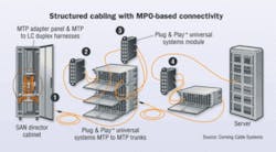
As an example, structured optical cabling has become anessential ingredient in efficiently scaling storage area networks (SANs) in data centers from hundreds of ports to thousands of ports. But implementing structured cabling alone may not be the entire answer to the problems in the data center. As more and more servers get networked into the SAN, limitations in traditional optical cabling solutions are exposed. In particular, cabinets housing SAN directors are scaling from hundreds of fibers to thousands. Deploying newer, modular, high-density cabling solutions in astructured cabling architecture offers the best practice for meeting physical layer requirements for manageability, scalability and reliability.
High-density, modular connectivity
Benefits of deploying modular, high-density optical solutions, such as MPO-based connectivity (including MPO trunk assemblies, breakout modules and breakout harnesses) in a structured wiring architecture include 50% cable-tray space savings, 80% improvement in deployment time, and 70% bulk-cable reduction in cabinets and racks. A modular, high-density solution deployed in a structured wiring topology can easily scale to hundreds of thousands of ports and significantly reduce the time to conduct MACs in the data center, thus reducing operational costs.
So now, we have the means to cope with future growth and churn in the data center. Now, let’s address the issue of keeping this modular high-density structured cabling system in place to handle future higher-data-rate applications.
In addition to manageability and scalability, a benefit to deploying a modular, high-density MPO-based cabling system is the available migration path to increased data rates. With some consideration of performance specifications, the infrastructure can easily migrate to future higher-data-rate technologies, such as parallel optics, which will be used in 32-, 64-, and 128-Gigabit Fibre Channel; and 40- and 100-Gigabit Ethernet. In fact, by deploying an optical cabling system that meets InfiniBand 12X-QDR (120-Gbit) cable skew performance requirements of = 0.75 ns and distance specifications, the same infrastructure that is carrying serial transmission today can be easily migrated to transmit parallel-optic InfiniBand signals.
The challenge, then, is to stay farsighted and to deploy the best combination of optical-fiber cabling and connector performance today to meet both current and future channel insertion loss budgets and distance guarantees for higher speed applications.
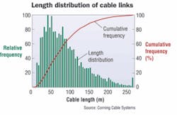
The majority of networking links in the data center are less than 150 meters, which enables the use of electronics with short-wavelength 850-nm VCSEL-based limiting transceivers. These lower-cost electronics are optimized for use with OM3 fiber, which has a bandwidth length product (BWLP) of 2,000 MHz*km, or four times greater than that of OM2 fiber. Specifying a higher grade fiber such as OM3 in thecabling infrastructure lowers power penalties associated with intersymbol interference (ISI) noise, and extends the operating distance when compared to OM2 and OM1 fiber at the same specified channel insertion loss.
Low-loss connectivity
An additional and important topic must be considered for improving the return on investment of a cabling infrastructure: Implementing a structured cabling solution with modular, high-density, MPO-based connectivity can increase channel insertion loss due to the increased number of connector mated pairs in the channel.
To ensure low BER, installed channel distances and channel insertion loss should be less than the distances and channel insertion loss specified in the particular standard. Exceeding link distances and channel losses result in exceeding system BER.
To mitigate this issue and increase the lifecycle of an optical-cabling infrastructure, deploy high-quality low-loss optical components. Low-loss MPO trunks, breakout harnesses, modules and jumpers minimize channel insertion loss and enable the cabling infrastructure to easily migrate to future higher data rates.
For example, 8-Gbit Fibre Channel will support a distance of 100 meters using OM3 fiber and a connector budget no greater than 2.4 dB. If an MPO mated pair has a maximum insertion loss of 0.5 dB, and each MTP-to-LC breakout module wasspecified at a maximum insertion loss of 0.75 dB, then theresulting maximum connector loss in the channel will be 2.75 dB.
This exceeds the recommended maximum 2.4 dB connector loss budget of 8-Gbit Fibre Channel at 100 meters, thereby reducing the supportable distance at 8-Gbit Fibre Channel; however, if low-loss components were specified into the same cable plant at 0.5-dB maximum insertion loss per MTP-to-LC breakout module and 0.35-dB maximum per MTP mated pair, then the resulting maximum connector loss in the channel will be 1.85 dB, providing support of 8-Gbit Fibre Channel beyond 100 meters.
As previously discussed, TIA-942 addresses the use of ZDAs as part of the recommended topology for datacenters. Implementing a distributed zone solution reduces pathway congestion and facilitates the implementationof MACs common in the data center environment. Implementing a zone topology can increase the number of connection points in a given channel. Using components with low-loss performance enables zone connectivity without sacrificing distance capabilities due to channel insertion loss.
Additional methods to implement zone distribution with reduced channel insertion loss include using components that are optimized for the architecture. Solutions that offer a combined MPO-based trunk assembly and breakout module can eliminate connector pairs while still offering the flexibility of zone cabling, thereby reducing total channel insertion loss.
An eye toward the future
Using low-loss components minimizes channel insertion loss and maximizes supported link distances. An infrastructure with these components provides for amigration path to future higher-data-rate applications, leveraging the likelihood of a long lifecycle for optical connectivity in the data center.
ALAN UGOLINI is manager of data center market development with Corning Cable Systems (www.corningcablesystems).
