Determining the best polarity for today’s and tomorrow’s data center cabling infrastructure
Methods A, B, and C each have their attributes. How can we take advantage of each?
By Dave Fredricks and Rick Dallmann,CABLExpress
In the data center space, we have seen an increase in speeds from Megabits per second (Mbits/sec) to Gigabits per second (Gbits/sec). During this time we have seen three MPO/MTP polarity methods approved as a standard from the Telecommunications Industry Association (TIA) within the ANSI/TIA-568 series of standard documents. (Hereafter this article will refer to MPO/MTP connectors using the brand name MTP.)
The three MTP polarity methods are described as Method A, Method B, and Method C. These three methods show light path (transmit to receive) using two fibers as duplex and twelves fibers as parallel connections. The three standards show MTP connectors as male (pinned) or female (non-pinned) and key-up or key-down orientation when mating in an MTP coupler. To better explore the three MTP polarity methods, understanding the components in each link is essential.

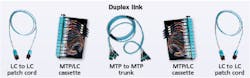
A duplex link comprises duplex patch cords at each end, plugging into MTP/LC cassettes. The MTP-to-MTP trunk is between the cassettes.
For a duplex link there is a duplex patch cord (LC to LC) on each end of the link. The duplex patch cord plugs into an MTP/LC cassette module on each end of the link. In between the cassette modules is the MTP-to-MTP trunk. The MTP connector has a key to ensure fiber positioning when mating. The MTP coupler that mates the connectors can be key-up to key-down, key-down to key-down, or key-up to key-up.
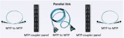
A parallel link comprises MTP-to-MTP patch cords at each end, plugging into MTP coupler panels, which connect to the optics. The MTP-to-MTP trunk is between the coupler panels.
For a parallel link there is a parallel patch cord (12-fiber MTP to MTP) on each end of the link. The parallel patch cord plugs into an MTP coupler panel on each end of the link, then into the optic. In between the MTP coupler panels is the MTP fiber trunk. The MTP coupler that mates the connectors can be key-up to key-down or key-up to key-up.
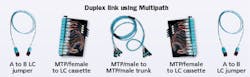
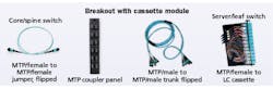
The Multipath polarity option uses an A-to-B jumper on each end of the link, and the same cassette module at each end. The MTP trunk is MTP/male to MTP/male.
With the duplex and parallel links there are polarity options for the LC-to-LC patch cords, the MTP-to-MTP patch cords, the MTP couplers as key orientation up or down in the cassette module and the MTP trunks. Mixing and matching these separate components can create confusion and nonfunctioning connections for the end user. Understanding the basic differences in each of the three MTP polarity methods can help determine which method to deploy.
With the Multipath polarity method, a 12-fiber flipped MTP/female-to-MTP/female jumper is on each end. The link also includes key-up to key-down MTP couplers and an MTP/male to MTP/male trunk.
Method A was the first to gain acceptance in the marketplace. It was easy to install because all the fibers were run as straight polarity. The MTP couplers were key-up to key-down for both duplex and parallel connections. The cross (transmit to receive) for duplex would occur with an A-to-B patch cord on one side of the link. The other side of the link would use A-to-A patch cord as straight polarity. The same idea occurs with the 12-fiber MTP-to-MTP patch cord. The flip (fiber 1 to fiber 12) corrects the light path for transmit to receive. One side of the link would have a flipped MTP patch cord while the other side would have a straight MTP patch cord.
Method A requires the end user to manage two separate duplex jumpers as A-to-B and A-to-A. For parallel links the end user needs to manage 12-fiber MTP patch cords as straight and flipped. Many polarity issues in the data center arise from these patch cord options. Method A requires the user to stock four polarity patch cords and to understand for which side of the link they are used.
Method B became popular when the data center space was beginning to support optics or transceivers that used 12- or 24-fiber MTP connectors. These optics were running 40-Gbit Ethernet or 100-Gbit Ethernet speeds. The thought was that the end user could easily go from duplex connections (ST, SC or LC) to parallel connections (12- or 24-fiber MTP). The data center operator could unplug a cassette module from the backbone or horizontal MTP trunk and insert an MTP coupler panel. This would switch the patch cord from duplex to parallel.
The challenge with Method B is that there are three different MTP couplers that can be used in the two link types of duplex and parallel. These are key-up to key-down, key-down to key-down, and key-up to key-up. Another difficulty with the mix of MTP coupler types occurs when the end user wants to install singlemode angled MTPs into the cabling plant.
Using this setup, a fiber-optic link can support optical signal breakout, such as 128-Gbit/sec Fibre Channel to 4x 32-Gbit Fibre Channel, 100-Gbit Ethernet to 4x 25-Gbit Ethernet, and 40-Gbit Ethernet to 4x 10-Gbit Ethernet.
With Method B there are two different cassette module types in a link—creating the need to stock two different part number cassette modules. But the duplex or parallel patch cords are the same for each side of the link, which is an improvement over Method A. Also, the ability to connect newer 12- and 24-fiber MTP optics is a benefit. As speeds in the data center move from 40-GbE to 400-GbE these parallel optics will become more common in the data center space.
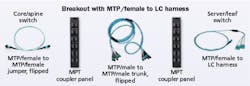
This setup—MTP/female to LC harness—also supports optical signal breakout.
Method C is more of a modification of Method A, and aimed at duplex connections. This method works well with storage applications running 2-, 4-, 8-, and 16-Gbit Fibre Channel that have been using duplex SC and LC connectors. It all works well with duplex connectivity for Ethernet that can support speeds up to 40-GbE for use with bidirectional optics.
Benefits of this method include enabling the end user to use standard A-to-B patch cords on both ends of the link. All the MTP couplers ae key-up to key-down. The cross of transmit-to-receive takes place in the MTP trunk. Both side cassette modules in the link are the same as straight polarity. The downside is that to convert from duplex to parallel links, costly conversion modules are required in place of the cassette modules.
To summarize, all three standard polarity methods can support duplex links effectively. Method B requires two different MTP coupler combinations, which can be cumbersome. These two coupler combinations result in two different cassette modules on each end of the link. Also when using angled singlemode MTP connectors this can be challenging to ensure proper alignment mating of the angled MTP ferrule.
All three standard methods can support parallel links, but Method C requires a conversion module that can add significant cost to the link. Also, conversion modules are not a standards-based product. Looking at the three published MPO/MTP polarity options, it’s easy to see that one solution for both transceiver types (duplex and parallel) in the market is challenging. They also don’t properly address the next generation of optics that will run 200-GbE and 400-GbE. As of today those speeds will be run on parallel optics as 24 fibers on multimode glass at 100 meters, and as 12 fibers on singlemode glass at 500 meters.
Another solution
At CABLExpress, we have been discussing this dilemma for several years, and we came up with a solution that we believe is best for the data center operator. The trademarked name for our solution is Multipath. We’ll describe it here.
The first part of the solution fulfills our desire to use only standard A-to-B duplex jumpers. We wanted to use only 12 fiber flipped MTP/female-to-MTP/female parallel jumpers. Both of these jumpers will plug into optic-to-optic connections and work properly, meaning transmit-to-receive. The end user only stocks one type of jumper for each type of optic.
As for the MTP couplers, we wanted to use key-up to key-down exclusively. The back of the cassette modules are MTP/female. With the same MTP couplers, the cassette modules on each end of the link are the same. This makes the migration from duplex to parallel links seamless. Simply remove the cassette module and install an MTP coupler panel. The MTP trunk is built as flipped light path similar to Method B, but always as MTP/male-to-MTP/male. This allows the use of 12-fiber flipped MTP/female-to-MTP/female parallel jumpers on the ends. Having a flipped light path backbone or horizontal trunk will work for the next generation of optics running 200-GbE and 400-GbE.
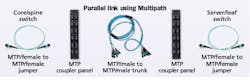
Multipath uses the same A-to-B duplex jumper on each end. It uses the same cassette module at each end as MTP/female. The MTP trunk will be MTP/male-to-MTP/male.
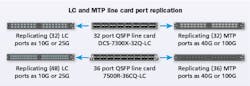
Depicted here is the replication of two Arista line cards.
It uses the same 12-fiber flipped MTP/female-to-MTP/female jumpers on each end. It uses the same key-up to key-down MTP couplers. The MTP trunk will be MTP/male-to-MTP/male.
To have links that require breaking out optical signals—like 128G Fibre Channel to 4x 32G Fibre Channel, 100GbE to 4x 25GbE, and 40GbE to 4x 10GbE—one end of the link would use a cassette module or MTP/female to LC harness.

To sum up, Multipath takes several advantages from each of the three standardized polarity methods. It uses flipped trunks to best serve parallel-optic connections. Most cabling vendors in the data center market recommend flipped polarity backbone or horizontal trunking. It uses the same duplex and parallel jumpers on both ends of the link. The cassette modules are the same on both ends of the link.

Multipath removes several of the polarity methods’ disadvantages, and removes the need for two different jumper types for duplex and parallel connections. It removes the MTP coupler positions of key-down to key-down and key-up to key-up. This in turn helps the move toward singlemode angled MTP connections using non-proprietary key-up to key-down designs.
Next-generation optics as of today will run 200GbE and 400GbE on 24-fiber MTPs on multimode glass. Multipath can support these connections simply by using a 24-fiber MTP/female into the optic and breakout into a 2x12-fiber MTP/female harness into the MTP trunk.
Recently there has been more movement to singlemode structured cabling designs. Most large equipment vendors now offer a 100GbE 12-fiber singlemode optic that will go up to 500 meters. The price of singlemode optics has dropped considerably in the past couple years and in turn increased in usage. These efficiencies of higher transport speeds and lower optic costs have been driven in part by the large cloud computing companies and their usage of these products. We believe that as data centers move toward 400GbE and beyond, they will deploy more singlemode fiber structured cabling systems.
Port replication
CABLExpress is a big proponent of port replication. Port replication is mirroring the ports of active fiber-optic hardware in a passive component (fiber patch panel), creating a direct one-to-one relationship between the active hardware ports and the passive structured cabling environment.
This allows switches to be cabled once, then replicated in a main distribution area (MDA), zone distribution area (ZDA), middle of row (MoR) cabinet, end of row (EoR) cabinet, or an individual cabinet. This action simplifies the cabling process with all numbers on the switches directly corresponding to the numbers on the patch panel.
When replicating LC ports with MTP to LC cassette modules, options come in increments of 8s and 12s—meaning we have cassettes that are 6, 8, 12, 16, 18, 24, 32, 48 and 64 ports. These nine different options help to replicate all types of vendor switch line cards and blades in large complete switch replication enclosures to smaller 1U solutions.
When replicating MTP ports with MTP coupler panels, options come with 6-, 8-, 12-, 16- and 18-port panels. As an example a 32-port QSFP line card is replicated in a 1U enclosure with two, 16-port MTP coupler panels. One panel is numbered from #1 to #16 and the second panel #17 to #32. The MTP ports directly mirror the 32-port QSFP line card.
Combining the Multipath structured cabling polarity solution with port replication hardware provides an efficient scalable fiber-optic plant. It supports current and next-generation optics. As the optics in the data center market increase in speed and diversity, the polarity solution described in this article will provide simple and logical components to connect the links.
Dave Fredricks is data center infrastructure architect and Rick Dallmann is senior data center infrastructure architect with CABLExpress.
Getting gender right with MPO connectors
By Bernard Lee, Senko Advanced Components
In recent years, optical connectors from the MPO family have become increasingly popular in the data center interconnect market. Specific brand names have emerged, including the MPO+, MTP, and SumiMPO, all of which are compliant to the IEC-61754-7 and TIA-604-5-D standards. These standard-compliant connectors are compatible and intermateable, hence they share some of the key features as stipulated in the standards documents.
A key feature is gender—male or female—in MPO connectors. Gender is relatively easy to identify visually. A male MPO connector has two alignment pins, while a female MPO connector has two alignment holes where the pins are to be inserted when a termination is made.
An MPO connection can only be performed between a male and female connector to ensure proper alignment, which is required to maintain a low-loss connection. As a general practice, the male connector usually is terminated in the patching back panel, wall outlets or transceivers, while the female connector is used at the ends of jumper cords. This practice keeps the male connectors in a static position to protect the guide pins from accidental damage. As technicians are sometimes unsure of the gender of the connector in use, some connector designs allow gender change in the field to ease and speed up installation.
As is the case with single-fiber connectors, the cleanliness of the total surface of a multifiber connector like the MPO also is critical to making a proper connection. The added challenge with male MPO connectors is that many traditional cleaners are unable to clean the alignment pins. Any contaminant around the optical fibers and alignment pin tends to prevent full contact of the two connectors. This creates an air space, which degrades the connector-loss performance.
Conventional MPO cleaning tools such as the pen cleaner clears contaminants around the optical fiber array. However, the space around the alignment pins remains contaminated. A new type of gel-based MPO cleaner would have to be used to remove oil, dust and dirt particulate from pin-to-pin on the connector endface. To perform the cleaning, the MPO connector is pushed into the cleaner, which sticks onto any contaminant, thus removing any particulate when the connector is removed.
Bernard Lee is regional technology director for Asia-Pacific with Senko Advanced Components.

