ANSI/TIA-606-B standard approved for publication

April, 2012 Issue of Cabling Installation & Maintenance Magazine
Specification coves a wide range of labeling and administration procedures, including data center environments, grounding-and-bonding systems, powered data ports and more.
By Todd Fries, HellermannTyton
At last, the new ANSI/TIA-606-B labeling standard has been approved by the Telecommunications Industry Association (TIA; www.tiaonline.org) Subcommittee TR-42.6, the Technical Engineering Committee TR-42, and the American National Standards Institute (ANSI; www.ansi.org). While more than 30 organizations participated in the development of this standard, its foundation is years of industry experience combined with years of feedback from users of the original TIA-606-A and then ANSI/TIA/EIA-606-A Addendum 1.
The new standard is intended to fully address the administrative needs of a data center as well as that of general administration.
ANSI/TIA-606-B is intended to be a generic labeling standard that applies to all types of premises. The standard is backward-compatible with the legacy ANSI/TIA/EIA-606-A Addendum 1 and is compatible with the international standard ISO/IEC TR 14763-2-1 identifiers.
The original TIA-606-A was designated to identify and record the general administration, but did not address the specific needs of the data center design and installation.
TIA-606-A was reaffirmed in 2007, and the TIA-606-A Addendum 1 was published in 2008. The addendum reconciled 606-A with the TIA’s 942 data center standard. In short, the current 606-A did not really acknowledge data centers and the 942 standard did not consider general administration. The two concepts came together in Addendum 1 to 606-A.
The development of the ANSI/TIA-606-B, combined the 606-A and the Addendum 1, and unified the requirements of the ISO/IEC TR14763-2-1.
Labeling is a key factor in the installation and maintenance of an efficient and professional installation. The 606 standard continues to expand and address how and where to identify key components of information transport systems (ITS).
Changes from last revision
The ANSI/TIA-606-B standard includes several changes from the last revision of the specifications, including the following six major changes.
1) Adopts identification scheme specified in TIA-606-A Addendum 1.

2) Creates new identification format for Cabling Subsystem 1 link identifiers (Horizontal links), Cabling Subsystem 2 and 3 links (Backbone cables) as well as telecommunications outlets, equipment outlets, splices, consolidation points and outdoor telecommunications spaces. (Note: In order to be generic to all types of premises, terminology was adopted from the TIA-568-C.0 standard in which Cabling Subsystem 1 is now what was commonly referred to as the “horizontal link.” The (1) does not mean anything in particular, except to differentiate Cabling Subsystem 1 links from Cabling Subsystem 2 and 3 links, which have been commonly referred to as “backbone” cables. Campus cabling has its own cabling separate from the Cabling Subsystem 2 and 3 links, which are the two layers of backbone cabling allowed in premises cabling.)
3) Extends administration to all inter-building telecommunications cabling
4) Administers Cabling Subsystem 2 and 3 links by pair groups, corresponding to ports rather than copper pairs or single fibers
5) Administration of grounding and bonding systems
6) Allows existing TIA-606-A identifier formats to continue to be used where they are already in use. (Note: An identifier is simply the “printed” text that will appear on a label as related to the standard.)
The basics
The fundamental point can be found in Section 4.4, in which it is explained that labels DO NOT need to include full identifiers. Only a portion of the identifiers is required to distinguish the component within the space in which it is located.

The basic premise of the data center implementation is actually very simple and can be broken down using a few common examples.
A typical patch panel and port identifier might be as follows: 1A.AD02-40:02
1A. = Floor 1, Room A
AD02 = The grid location within the data center for a particular rack or cabinet
-40 = A patch panel located 40 rack units from the bottom of that rack or cabinet
:02 = A specific port within the patch panel located at AD02-40. (This can also be a range of ports, 01-24 as an example.)
Optionally, we can remove the space location to the front of this identifier. If we are on Floor 1, Space A, and this is the only space, there is no need to include that portion on the printed identifier. The actual printed identifier might look as follows: AD02-40:02.
Because we are harmonizing to the ISO/IEC TR 14763-2-1, we can optionally add a “+” sign, which specifies that the next portion of the identifier is a location aspect. The “+” sign only needs to appear in the records section and not on the actual label: +AD02-40:02.
An “=” in front of an identifier specifies a function aspect (example: =XO for telecommunications outlet).
Classes of administration
The standard still breaks out the criteria by classes of administration.
Class 1—Locations served by a single Equipment Room (ER). This ER is the only Telecommunications Space (TS) administered, whereas there are no Telecommunications Rooms (TRs) and no Cabling Subsystem 2 and 3 cabling or outside-plant cabling systems to administer.
Class 2—Completes the administration needs of a single building that are served by multiple TRs with one or more TRs within a single building. This includes all the elements of a Class 1 system plus identifiers for Cabling Subsystem 2 and 3 cabling, multi-element bonding and grounding systems and firestopping.
Class 3—Serves a campus environment with multiple buildings and building pathways, spaces and outside-plant elements.
Class 4—Attends the needs of a multi-site (multi-campus) administration.
There are slight differences in requirements depending on what level is administered. For example, in a Class 1 system the floor and room number do not need to be identified because there is only one room to manage. Obviously, as the complexity of the system increases, additional identifiers are needed. In Class 3 and 4 systems there are additional requirements, such as building and campus identifiers, along with outside-plant and inter-campus elements such as wide area network connections. We will address these as well.
Space, cabinets and racks
As an example of space labeling, 1A = Floor 1, Space A, which is an alpha-numeric sequence that can be edited to suit the needs of the installation. For example, 3TRA would represent Telecom Room A on the third floor. An example of an ISO/IEC TR 14763-2-1-compatible format is +3TRA.
The standard recommends the use of grid coordinates to distinguish the rack or cabinet in a space. In rooms that have access-floor systems, recognition for the space shall employ the access-floor grid identification scheme using alpha and numeric characters to mark the X and Y coordinates within the space.
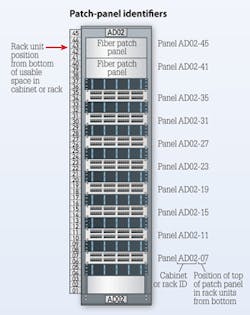
To illustrate, a rack located at grid coordinates AD02, would be marked as AD02. Typically the label is placed on the top and bottom, front and rear of the rack or cabinet using machine-printed labels. Where grid coordinates are not used, the racks can be marked by row and rack number.
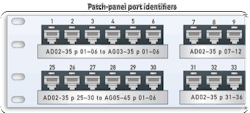
Patch-panel and port identifiers
Within each rack, there will be patch panels. The patch panels shall be labeled with the identifier of the patch panels at the far end of the cables, if practical. These should be marked using rack units from the bottom of the cabinet. Because the floor/space marking is optional in a Class 2 system, the rack and panels can be marked simply by combining the grid coordinates of the rack with the rack units of the panels within that rack. A patch panel that is 35 rack units from the bottom of a rack located at grid coordinates AD02 would be identified as AD02-35.
The patch panels shall be labeled with the identifier of the patch panels at the far end of the cables, if practical. Each port, the first port or the last port, or the last of each subpanel, shall be labeled. Patch panel labels shall contain the patch panel identifier. Where space permits, the patch panel also should have labels to specify the classification at the far end ports using this format. Each panel will have a series of ports that need to be acknowledged.
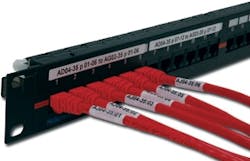
Thus, a typical patch panel/port identifier on a set of six ports within the patch panel might be marked as: AD02-35 p 01-06 to AG03-35 p 01-06.
This defines the near-end set of six ports located in a patch panel 35 rack units from the bottom of the rack or cabinet at grid location AD02, and these ports are going to be the “far-end” set of six ports located in a patch panel 35 rack units from the bottom of a rack or cabinet at grid location AG03.
Please note, the near-end room name and near-end patch panel identifier can be omitted because this information is implicit and inferred from the required cabinet/rack and patch-panel labels. (Section 5.1.3.1.3.1 of the standard addresses this issue.) This means that the length of the identifier can be truncated to save space yet keep the format intuitive to the user.
As an example, one could shorten the example above to “p 01-06 to AG03-35 p 01-06.”
Patch panels that support Cabling Subsystem 2 or 3 should indicate the name of the space: Main Distribution Area (MDA), Intermediate Distribution Area (IDA), Horizontal Distribution Area (HDA) or TR, to which the cables run. Example: Ports 01-06 to HDA01 AJ17-45 Ports 01-06.
All ports on patch panels and all positions on termination blocks shall be labeled with the corresponding port number or position number and optionally with additional identifier fields as practical. All subpanels shall be labeled with their subpanel identifier. An example of a subpanel identifier usually is indicated by an alpha character, as in the following example.
Ports A1-A6 & B1-B6 to AG10-B Ports 01-12
Ports A1-A6 = Subpanel A, ports A1-A6
Ports B1-B6 = Subpanel B, ports A1-A6
AG10-B – Subpanel B in rack at grid location AG10
Ports 01-12 – Ports 1 to 12 in subpanel B
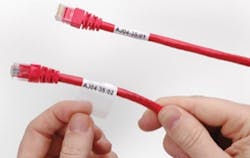
Certain applications may provide electrical power in addition to data transmission over balanced twisted-pair cables. Visual identification of ports with power may be accomplished through the use of the symbol shown on page 14. This symbol can be included anywhere on the label.
Specialized applications
The new standard does address unusual and constantly changing circumstances. For example, several manufacturers have come out with cabinets that use zero rack-mount space by incorporating vertical rails in the cabinet to save space. In short, additional patch panels reside on either side of the cabinet in a vertical position.
In this case, how does one identify these vertical patch panels? A simple way to mark the vertical panels is to use rack units combined with an alpha character for location within the rack or cabinet. The TIA-606-B now designates an additional alpha letter indicating the side as A, B, C, D or F, L, R, B (Front, Left, Right, Back) as examples. This can be used when rack units (RU) are assigned. The user is able to name the horizontal and vertical patch panels by rack unit. The rack unit of the vertical patch panel is determined by the rack-unit location, of the height of the top of the vertically mounted patch (by height at the top). A separate alpha designation for Right (R) or Left (L) is used to distinguish the vertical patch panels as being either on the left or right side of the cabinet.
Example: AG09-L35:01-06. In this case, the credential is describing a patch panel at 35 rack units from the bottom of the rack, on the left side of the cabinet, at grid location AG09, ports 1 to 6.
Using preterminated copper or fiber solutions, zero-U, height-density cabinets can allow additional ports where needed and aligns connectivity with the servers. This allows for moves, adds and changes without interrupting rack-mounted equipment in a fully populated cabinet. This is a new trend in cabinet management to maximize data center real estate. Thankfully the new TIA-606-B standard is flexible enough to allow proper identification of these vertical panels.
Cabling Subsystem and Horizontal links
The main focus of the 606-B standard is the ability to track the ITS from the data center to the work area. Using the new format, a horizontal link identifier that terminates at both ends on panels within the same data center would be printed as follows:
Near end = AG09-35:01/AJ06-35:01
Far end = AJ06-35:01/AG09-35:01
If standing at rack location AG09, reading this near-end cable identifier will describe both the near-end and far-end locations.
AG09 = Rack or cabinet at grid location AG09 within the data center
-35 = Patch panel located 35 rack units from the bottom in rack AG09
:01 = Port 01 in patch panel located 35 rack units from the bottom of rack AG09
/ = Separator for near-end/far-end location description
AJ06 = Rack or cabinet at grid location AJ06 within the data center
-35 = Patch panel located 35 rack units from the bottom in rack AJ06
:01 = Port 01 in patch panel located 35 rack units from the bottom of the rack in AJ06
The ISO/IEC TR 14763-2-1 identifiers would appear as follows for a Cabling Subsystem 1 Link: AG09-35:01/AJ06-35:01=W. The “W” is the letter code for cables as specified in IEC 81346-2.
Note that in commercial buildings, industrial premises, data centers and multi-tenant buildings, each individual telecommunications outlet or equipment outlet shall be labeled with the Cabling Subsystem 1 link identifier. The labeling shall appear on the connector, faceplate and multi-user telecommunications outlet assembly (MUTOA) in a way that clearly identifies the individual connector associated with the particular identifier.
Using the Cabling Subsystem 1 link identifier, it is optional to identify Equipment Outlets (EOs) and Telecommunications Outlets (TOs) by using a two-letter code to identify the outlet.
XO = Equipment Room outlet
XC = Consolidation Point
XL = Zone Distribution Area (ZDA port
XSz = Splice where “z” is the appropriate distance along the cable of the splice from the termination point in the TR or HDA.
An example of a Cabling Subsystem 1 link identifier using the option to identify the outlet might look as follows: AG09-35:01/AJ06-35:01=XL:5
The port on the consolidation point may optionally be identified by a colon “:” and the port after the XL.
Grounding and bonding
The TIA-606-B covers grounding and bonding in greater detail than previous versions. An example might be a rack grounding busbar (RGB) identifier where you may have more than one RGB in the cabinet, rack or wall segment as shown here: 2A=RGB1
2A = Floor 2, Room A
RGB = Rack Grounding Busbar #1
The standard also allows the addition of an identifier that describes an object to which the bonding conductor is attached. This might include an electrical panel, a pathway, building steel, a cable tray, or equipment such as a local area network switch. Typically, this is the TIA-606-B identifier of the equipment. In this example, we add the grid location of the rack or cabinet to which the RGB is attached: 2A=RGB1/AJ05
2A = Floor 2, Room A
RGB = Rack Grounding Busbar #1
AJ05 = Rack at grid location AJ05, which is the object attached to the RGB.
Subsystem 2 and 3 identifiers
The backbone cabling is handled very similarly to Cabling Subsystem 1 link identifiers explained earlier in this article. A typical identifier will include the marker for the space at one end of the cable, the space terminating the other end of the cable, and one or two alpha-numeric characters to identify a single pair or port.
1A.AJ06-27:01/2A.AJ09-27:01
1A = Floor 1, Space A
AJ06 = Rack or cabinet at grid location AJ06
27 = Patch panel located 27 rack units from the bottom of the frame
:01 = Port 1
For Class 3 and 4 installations, the installer is just adding campus and building identifiers. Example of a backbone cable identifier:
A-ENG-1A:AJ06-27:01-06/B-ADM-1A.AJ09-27:01-06
A = Campus A
ENG = Engineering Building
B = Campus B
ADM = Administration Building
Please note that administration of Cabling Subsystem 2 and 3 identifiers is by pair groups or ports rather than copper pairs or single fibers. Each port or pair on a building Cabling Subsystem 2 and 3 cable shall have a unique identifier. Individual optical fibers and balanced pairs are typically color-coded rather than individually marked.
Firestopping
The TIA-606-B legacy format for marking a fire stop would be printed as follows.
2-FSL01(6)
2 = 2nd Floor
-FSL = Fire Stop Location
01 = Location
(6) = 6-hour burn rating
The comparable format for ISO/IEC 14763-2-1 would be printed as follows.
SF02-2A/3A=U(3)=F
SFO2 = Building SF02
2A = Floor 2, space A
/ = Located between telecom rooms 2A and 3A
3A = Floor 3, space A
=U = U following the = specifies the element is a pathway
(3) = Sleeve 3
F = Specifies the element is a fire stop location
Colors and records
Using colors is recommended but not a requirement. Smaller installers find it costly to stock and purchase many colors of labels in order to meet a requirement that might not fit their particular situation. The 606-B is not color-dependent and allows the installer to fully identify without requiring the use of color. If color is used, the installer should use the pantone color scheme as outlined in Section 10.2.2, Table 4 of the 606-B standard.
Most installers are aware of the cost of installing and maintaining an efficient and cost-effective ITS. Labeling is crucial in this area. Yet there is an aspect that is often neglected—record keeping. Maintaining records of your ITS installation is the most valuable part of any labeled configuration. In the standard, you must link a record for each identifier that is printed on a label. If the records are complete and accurate and contain the recommended data as outlined in the labeling standard, the customer will have a well-documented infrastructure that can be understood and managed by anyone responsible for making moves, adds or changes.

So the label is important, but if you do not attach the relevant data to that identifier, much of that value is lost. A database can be something as simple as an Excel spreadsheet. Each identifier makes up a row in the spreadsheet and each element associated with that identifier is recorded in the columns going across the database.
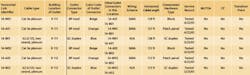
For example, each Cabling Subsystem 1 link (Horizontal link) record shall include the following.
Location of work area outlet connector
Cabling Subsystem 1 link identifier
Outlet connector type (e.g., 8 position, 110, SC or duplex)
Crossconnect hardware (Patch panel, T568B Category 5e, etc.)
Cable type (e.g. 4-pr UTP, Cat 5e, plenum; or 2-strand 62.5/125 multimode, FDDI grade, riser)
Cable length
Service record of link
It may also include any other data that the installer or customer believes is pertinent to the installation such as the color code of the outlet connectors, wiring scheme, MUTOA, consolidation point or transition points. It could be shown in the form of an Excel spreadsheet, as demonstrated in the table shown on pages 8 and 9.
If the ITS is not efficient to administer, the cost of any mistakes far outweigh the initial cost of recording all the data at the time of installation. In the long run, the expense of not recording administration data can be very high. The outlay of testing and tracking cables can be expensive and can result in a backlog of cables that are abandoned in the plenum in lieu of simply pulling a new cable. Even an installation that appears intuitively simple may grow over time and eventually become an unmanageable mess if the ITS is not recorded properly.
The TIA-606-B standard is the culmination of years of work by many experts, installers, engineers and customers to make the best system possible. There are still elements that must be addressed, but it is a standard that has global attention. It is a paradigm that will continue to develop and change the way we think about administration and labeling.
Todd Fries is marketing manager, identification systems for HellermannTyton (www.hellermanntyton.com).

