Updated bonding standard on shaky ground
As the TR-42.3.1 Working Group embarks on a rewrite of the 607 bonding and grounding standard, controversy and differences of opinion surround a number of key issues.
by Betsy Ziobron
For years, telecommunications bonding and grounding has been a controversial topic, with differences in expert opinion and a variety of methods from vendors causing plenty of confusion among those who design and install bonding and grounding infrastructures. Driven by today"s high-performance copper cabling systems, there is now an outpouring from the industry asking for guidance and unambiguous clarification.
That, combined with TIA"s (www.tiaonline.org) five-year standards revision cycle, has prompted the revision of ANSI/EIA/TIA 607 Commercial Building Grounding and Bonding Requirements (J-STD-607-A), and the TIA 42.3.1 Working Group has the arduous task ahead of reaching consensus on a number of key bonding issues.
Originally written in 1994, ANSI/EIA/TIA 607 was the first United States standard to address bonding and grounding for the telecommunications industry. Revised and republished as a joint standard in October 2002, the current version of J-STD-607-A is now in the hands of TIA"s TR-42.3.1 Premises Telecommunications Bonding and Grounding Working Group, which has begun the process of accepting contributions and updating the standard for what will ultimately be TIA 607-B.
Details to add
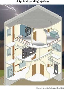
"The biggest driver for the rewrite of 607 is the need to provide more detail and direction on how to bond from the equipment in the rack or cabinet to the TMG [telecommunications grounding busbar] and TMGB [telecommunications main grounding busbar]," says Mark Harger, chairman of the TR-42.3.1 Working Group and president and owner of Harger Lightning and Grounding (www.harger.com).
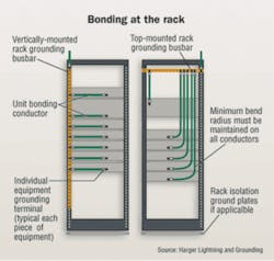
"There are many opinions on bonding equipment and racks," Harger continues. "Some will use a vertical rack busbar that runs the length of the rack. Others will use a horizontal busbar across the top and run longer bonding conductors from the equipment. From a cable-management standpoint, the vertical busbar enables the use of shorter conductors, but it also depends on the rack and equipment manufacturer, and the size and amount of the equipment."
The current 607 standard states that equipment and racks need to be bonded, but does not specify how. Nonetheless, much of the confusion comes more from equipment vendors.
"Depending on which manufacturer you talk to, there can be completely different bonding and grounding schemes specified," says Rich Jones, director of global standards with Chatsworth Products Inc. (CPI; www.chatsworth.com). "We are encouraging equipment manufacturers to participate in the rewrite of the 607 standard so we can understand how bonding and grounding impacts the performance of their equipment and why they"ve specified some of the methods they have."
Some are also calling for additional information on specific applications, such as towers and antennas, data centers, wireless systems, industrial applications, and residentialinstallations. "It"s too early to tell if specific applications will be addressed in the standard or as addenda, but there are some specific bonding and grounding methods that you might do in a data center or other application that are above and beyond what"s required for ageneric commercial system," says Harger.
The TR-42.3.1 group, Harger adds, has also discussed the possibility of addressing surge protection—something that is not in the current 607 standard. "The issue of surge protection was not originally included because it was not part of the primary intent to establish a grounding and bonding infrastructure for telecommunications," he explains. "Installers know they need to meet the NEC [National Electrical Code] for surge protection, and it remains to be seen if that topic will make its wayinto the rewrite of 607."
Up for debate
Bonding to the building steel is one of the controversial topics up for debate. The current 607 standard states that each TGB and the TMGB should include a supplemental bonding connection to the metal frame of a building in addition to the telecommunications bonding backbone (TBB) that bonds all TGBs with the TMGB as part of the telecommunications pathways and spaces (independent of cable).
"Many international and military standards allow the use of the building steel in lieu of the TBB, not in addition to it," says Harger. "Many in the industry don"t believe that the building steel can be easily verified for continuity, but there are methods available for testing that. It"s definitely one of the more controversial topics that we"ll be dealing with, and we will look to the experts as well as other standards for reference."
One of the biggest bonding and grounding arguments among experts is whether a single- or multi-point system is better. With single-point grounding, all electrical and telecommunications systems are grounded at a single point, which has long been recommended in industrial applications for its ability to reduce noise generation. In multi-point grounding, systems aregrounded at multiple points.
"As technology advances, more and more equipment manufacturers are specifying a combination of performance and safety bonding and grounding," says Jones. "The current 607 standard allows for both single-point or multi-point, and some equipment vendors recommend one and some recommend the other. That"s just another reason why we need these vendors to participate in our effort to rewrite 607."
Jones continues, "There is confusion surrounding the difference between safety and performance grounds;607 is primarily about performance of high-bandwidth applications, while the NEC is concerned with safety. One is not a substitute for the other."
He adds, "You can"t assume that a good telecommunications performance grounding system is all you need forsafety, and you can"t assume that a good electrical safety ground is all you need for today"s IT performance. Both are needed, and they must be installed properly to work in harmony with one another."
Clarifying shielded
With screened and shielded cabling systems receiving more attention as a viable option for avoiding alien crosstalk in 10-Gigabit Ethernet over copper applications, many in the industry are asking for clarification on the proper method for bonding shielded cabling systems. Much of the confusion surrounding bonding of shielded cabling systems has been caused by much misunderstanding as well as myths that have permeated the industry.
"It"s a disappointment that so many installers havebelieved the myth that screened and shielded systems are difficult to bond and ground," says Valerie Maguire,global sales engineer with Siemon (www.siemon.com). "These systems require just one additional step: A 6-AWG bonding conductor from the shielded patch panel to the TMG in the same way that other equipment is bonded.The screen of the cable is bonded to the patch panel during termination, and the 6-AWG bonding conductor from the patch panel to the TMG simply maintains the continuity of that screen to ground. This is not required for UTP because there is no screen connection."
A frequently-asked question is whether a shielded system needs to be bonded at both ends—at the workstation and at the telecommunications room—or at one end. For a channel, the ground at the workstation is achieved through whateverpiece of equipment is installed there; however, many stillbelieve that bonding shielded systems only at the telecommunications room will create an antenna effect.
"For proper performance, you only need one ground connection," Maguire explains. "Most screened and shieldedcabling systems have three: one through the computer at the workstation, one at the patch panel, and one through the network equipment. There is absolutely no reason to provide a fourth ground connection at the workstation outlet. Even if someone uses a UTP cord at the workstation or removes the ground by using a battery-powered laptop, there is no degradation in performance because you still have a connection to ground in the closet."
Maguire adds, "The idea that the screen of shielded cablecan create an antenna is absurd. It"s ridiculous to think that a long length of aluminum foil is more likely to pick up a signal thana low-impedance, 24-AWG copper conductor. We"ve tested both UTP and shielded for the antenna effect, and the degree to which they can pick up noise in the commercial environment is sominuscule that you really can"t call either one an antenna. In fact, a shielded system is 100 to 1,000 times less likely pickup noise in the environment. The antenna myth has been completely dispelled every which way you look at it."
Maguire also points out that shielded systems can measure for ground loops, which don"t necessarily affect datatransmission but could affect equipment performance: "With UTP, there"s no way to see if there"s a difference in ground potential between the telecommunications and electrical systems, because there"s no shield to accessthe ground connection on the cable. Shielded offers theadvantage of being able to easily make that verification."
While TR-42.3.1 is discussing just what the 607-B standard will include when it comes to shielded systems, Maguire says it"s as simple as stating that in addition to all the requirements that apply—regardless of media—for ashielded system, you shall also provide a low-impedance ground from the patch panel to the TMG.
"I don"t think the standards need to address the myths of bonding at both ends and the antenna effect, but it would make a great informative bulletin," Maguire says. "Siemon, among others, has gone through great efforts to make this information available through white papers andother means, and users have been very appreciative of the information. I"m sure they would value the same information coming from the TIA."
Collaboration is key
With so many different opinions and uncertainties even among the experts, the TR-42.3.1 Working Group has the daunting task of coming to an agreement on many bonding and grounding issues, and as chairman of the committee, Harger doesn"t think that the standard will be ratified this year. "We have no idea when it will be completed," he says, "but contributionswill be coming in over the next few months followed bymonthly conference calls to discuss and vote on issues."
There is, however, agreement when it comes to emphasizing bonding over grounding. The name of the standard will change from "grounding and bonding" to "bonding and grounding" because the TIA recognizes that the telecommunications system is technically bonded to the electrical ground, and installers are not really grounding at all.
"We all agree that we need to put more emphasis on bonding," says CPI"s Jones. "We also all agree that the industry is clamoring for guidance, and there is room for improvement."
BETSY ZIOBRON is a freelance writer and regular contributor to Cabling Installation & Maintenance. She can be reached at: [email protected]


