Making informed power-protection decisions
A site survey, good grounding practices, and proper transient protection are the three fundamentals of power protection from transients.
Chris M. Constance, Northern Technologies Inc.
Let`s suppose you are the operations manager for a Mobile Communications Central Office (mcco) in the Midwest. It`s springtime and the humidity and lightning activity have increased in the last few weeks. At two in the morning, you are awakened by the call you`ve been dreading. A lightning storm has passed through the area and taken your mcco offline. You think to yourself, "I had transient protectors installed. What could have happened?"
Once at the office, your worst fears are realized when you assess the extent of the damage. All of your rectifiers powering essential DC loads have been damaged. You have only a couple of hours of battery time remaining, and you discover your series protection panel has also been blown and there is no way to bypass it to pass through commercial power, which has now been restored, or even backup generator power. Furthermore, virtually all of the billing and computer equipment has been fried, including the data-line interface cards between processing centers. As the body count of damaged equipment and the turmoil created by lost service and upset customers increases, you wonder, "How could this have happened? What should I have done differently?"
Unfortunately, in this hypothetical case you could solve the problem only after the damage had been done. But you can be proactive about site protection and avoid such costly damage before it occurs.
The first step toward improving power protection is to schedule a site survey in which you inspect the integrity of grounding and bonding and assess the transient preparedness of your site. Use the survey to prepare an electrical schematic, or one-line, of the site. It is vital to walk through the site during this survey so you can get an accurate one-line, because facilities change over time and blueprints may not reflect current electrical configurations.
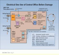
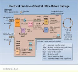
At our midwestern mcco, for instance, Utility Feed #1 was the commercial supply for most of the equipment at the site, including the critical rectifiers and DC power center. To provide protection, a transient-voltage surge suppressor (tvss) was installed off of a breaker in the 400-amp main distribution panel (mdp). It was a metal-oxide varistor (mov)-based device, installed 14 or 15 wire-feet away from the protected panel.
Upstream from Panel lpb was a series tvss device that passed the load current and was installed with no means of bypass. Other small, mov-based devices were installed at panels lpb and lpc. Some heavy-duty, less-sensitive loads, such as the heating, ventilating, and air-conditioning system and lighting, were fed from Panel lpa.
Utility Feed #2 had recently been added to the site; it fed a separate part of the building, which housed general-purpose office equipment, computers, lighting, and other items. These devices were fed off Panel ofs. Several computers in this area connected, via outside data lines, to billing computers fed from Panel lpc. There were no tvss devices protecting any loads fed from Panel ofs and no data-line protection at all.
Grounding needed first
The deficiencies in the transient-protection system for this site required attention, but, first, careful consideration had to be given to the site`s grounding system. Without adequate grounding, even the most comprehensive transient-protection strategy will be undermined.
Grounding at the mcco site was done in stages. During initial construction, the tower had several 10-foot ground rods placed near its legs; these were bonded with a buried ground ring. The neutral-ground (N-G) bond at the AC service entrance was tied to another 10-foot rod driven near the meter/main disconnect base. Other ground rods were driven around the perimeter of the site, and internal ground bars and equipment chassis were bonded to these rods. The AC service entry grounding point, the tower buried ground ring, and the equipment grounding rods were not bonded in any way.
An additional ground rod was driven for Utility Feed #2, and this also was isolated from other grounds at the site. Later inspection of the N-G bonds and other connections to the driven rods revealed that most were made with partially loose and corroded mechanical clamps, with many tight bends in the ground leads.
An entire book could be devoted to proper grounding techniques, but only a few major recommendations will be discussed here. First, the isolation of the separate grounding systems created the possibility for ground loops, because the ground paths for several systems could be traced to different (and isolated) rods.
In addition, this arrangement of grounds makes possible an uneven rise in ground potential. When a high-energy transient or surge is introduced, either on the tower or through incoming AC transmission lines, that energy attempts to complete its path by searching for a low-impedance path to ground. As the thousands of amps of current are diverted to the ground plane at the tower buried ground ring, for example, step potentials are created around that point. This means that locations only 4 or 5 feet away may have a potential difference of thousands of volts because of the resistance of the surrounding soil.
When two reference areas, such as the tower buried ground ring and another driven rod connected to equipment chassis or coaxial-cable sheath grounds, have a connection path between them, you have the two necessary components for possible equipment damage: a large potential difference under transient conditions, and a path for current to flow.
Typically it is the equipment along this path, such as the radios or other rack-mounted equipment whose chassis are referenced in this case, that becomes the fuse.
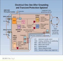
The remedy to this situation at the mcco was to bond the separate grounding rods and halos together at the site, creating a single-point ground. In this case, when transient energy reaches the site and is diverted to ground, the entire site will rise and fall together in potential. Another grounding practice that improved the site involved guaranteeing that ground bonds were made in a way that supported solid, long-term integrity: Exothermic welds or compression clamps were used for critical bonds to driven rods. Where mechanical clamps were made, surfaces were treated with non-oxidizing lubricants, and double-bolt lugs were used to prevent corrosion and loosening. All ground leads were of adequate size (#2-4/0 awg) and free of tight bends, for lower impedance at high transient frequencies.
A rough schematic of a single-point grounding scheme for the site shows how isolated grounding points have been joined together.
Another major area of concern was the integrity of the N-G bonding points for both utility feeds. A good bond will deter common-mode problems. These result from impulses and noise that are common in amplitude and polarity with relation to ground entering the line and neutral conductor, because the conductor is adequately connected to ground, thus eliminating the N-G impulse. The subsequent normal-mode disturbance, which results from an impulse referenced between line and neutral, will be handled by properly installed tvss devices.
Initially, the N-G bonds in the service disconnect cabinets at our example site relied on the metallic cabinet as a conducting path. This was changed to provide adequate #2/0 awg jumpers between the neutral and ground buses; they were continued down to the rod driven in the earth.
Transient protection needed
With the grounding system improved, attention could now be directed to the critical transient-protection system. It was discovered that the series tvss device and the small, hardwired mov units had sacrificed themselves during the failure. However, the front-end, brute-force mov unit off the mdp had not been damaged at all. Even though protection devices had been installed, the site would have had a better chance of survival had better choices been made regarding the technology used and the configuration of the installation.
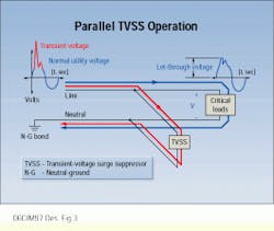
A transient-suppression device or system is often placed in parallel, electrically, with the critical system or equipment it is designed to protect. This configuration provides an unobtrusive means for the suppressor to influence the let-through voltage seen by the downline load, without the possibility of leaving that load without power if the suppressor were to sacrifice--as in the case of a series protector installed with no means of bypass. This is exactly what happened at the mcco in our case study.
Under normal conditions--where the voltage is within safe operating tolerances for vital equipment--the parallel suppressor remains in a high-impedance state, which restricts the flow of any load current through the protection device. When the voltage varies in either polarity above the clamping level designed for the suppressor (usually plus or minus170V peak for a 120V root-mean-squared system plus or minus20% to 25%), the device will change to a very low-impedance state--virtually a short circuit--and it will divert the harmful transient energy away from the sensitive downline load for the duration of the overvoltage condition.
For adequate protection of sensitive solid-state devices, the most critical factor is to limit the above-nominal voltage seen across the terminals of the tvss, often called let-through voltage. This factor characterizes the suppressor`s performance and yields its UL-1449 rating under specific testing conditions.
The design of suppression components such as movs or silicon avalanche diodes (sads) determines clamping voltage. The manufacturer`s specification of the voltage at which these components begin to clamp is usually based on one milliamp of current applied across the device`s terminals. The industry standard specifies a peak current component of 3 to 10 kiloamps, based on an 8 x 20-microsecond waveform, to simulate transient events for protection device testing.
An equipment owner has some latitude in choosing the magnitude of the clamping voltage, depending on the manufacturer`s specifications, but these values are usually common among tvss manufacturers and are set approximately 20% to 25% above the nominal peak voltage. This allows for small variations caused by system fluctuations, but it limits potentially harmful transient spikes to safe levels.
Equipment owners do have complete control over selecting technology and design, and it is these factors that will differentiate the relative quality and performance of installed tvss devices. Though the values of the impedances involved in specifying these devices may be relatively small, when they are multiplied by the tremendous surge current, their effects are magnified enormously.
At the mcco site, it can be seen in the initial installation that there were some mov-based devices placed near the mdp and downline at panels lpb and lpc, with a series protector between them.
movs and sads are common components used today for AC power protection. They are both nonlinear devices whose impedance changes from roughly an open circuit at voltages below their clamp threshold to that of a virtual short circuit once these thresholds are exceeded. Each has its own finite impedance value when it is conducting current (Z"on"), however, which is critical for determining how the device will limit let-through voltage to the downline load.
Test results clearly show the advantage of the low impedance value (Z"on") produced by sads. When it comes to protection of sensitive equipment, every volt counts, so choosing a primary technology with an inherently low "on" impedance, such as sads, will enhance suppressor performance. Because they are relatively inexpensive on an energy-rating basis, however, movs serve as an excellent backup in tvss design.
Furthermore, movs degrade with current flow. Lifetime ratings can be obtained from mov manufacturers that show their expected longevity based on the amplitudes and durations of applied transient waveshapes. sads, on the other hand, will operate indefinitely, provided their energy ratings are not exceeded by an incoming pulse. Therefore, careful consideration must be given to system vulnerability and exposure levels in order to make adequate choices in this area.
Multilayered protection
An effective strategy for many large installations is multilayered power protection. This can involve placing a brute-force, mov-based device near the AC service entrance, where less sensitive motorized loads are located. These loads require less stringent clamping characteristics than does more vulnerable downline equipment. The latter requires tvss devices using sad technology. This approach allows the frontline protectors to knock down a potentially catastrophic incoming lightning transient, while subsequent sad primary suppressors clean up the residual disturbance. Such an approach was employed for the rewired mcco and has proved to be extremely effective. Each protection system, however, should be engineered on a case-by-case basis to guarantee that all vulnerabilities and variations are accounted for.
For the central office, it was recommended that the existing mov device be kept, with improved installation, and that properly sized protection units using sad primary technology backed up by mov secondary stages be installed at all critical subpanels from both utility feeds. Deciding on the proper tvss panels was the initial step. It was also critical to install the devices for optimum performance. This meant keeping parallel-path impedance to a minimum.
Virtually every aspect of connecting a suppressor to the surrounding electrical system it is designed to protect impacts parallel-path impedance. Normally, the protection device manufacturer`s installation instructions include recommendations to maximize protector performance. If this is not the case, these key concepts should be kept in mind:
- Install a parallel suppressor as close as physically possible to the protected load center to minimize lead length.
- Use wires with larger crosssectional area, such as #4 to #2 awg, and route them so they are free of tight 90o bends, which restrict the flow of high-frequency (100-kilohertz to 10-megahertz) transient energy.
Why were no modules lost in the brute-force mov device during the failure? Probably because the 14- or 15-foot wire length led to a let-through voltage so high that the device barely responded to the incoming surge. For the mcco, it was recommended that the device be installed against the mdp to minimize lead length. This procedure was also followed with the downline dual-stage sad/mov protectors. Also, the undersized series protector was removed, along with the smaller hardwired mov devices at panels lpb and lpc.
With the front-end AC powering system protected by such multilayered defenses, the computer systems should have been safe. Was there a blind spot not yet accounted for?
Comprehensive site protection must take into account every possible entry point for harmful transient energy. The AC and telephone utility lines are the most obvious connections to the outside world. We can think of them as lightning`s "front doors." Data lines connecting local area networks, printers, or other peripheral equipment may connect to collocated structures or have exterior runs of cable; they can be a "back door" for transient energy. To solve this potential problem, data-line protection devices were placed on both ends of cables connecting computer equipment, as seen in the revised mcco one-line.
All sensitive systems at the site have enjoyed comprehensive protection since the audit recommendations were followed. Although there has been continued lightning activity and an occasional sacrificed protection module, the modules have been replaced overnight through the warranty program and field-replaceable maintenance, so that the full protection status of the facility has been maintained. Protection modules are easy to replace and are inexpensive in relation to the investment in network infrastructure and the potential for lost revenue, not to mention an even more critical corporate asset--the trust and confidence of customers.
The goals of ensuring adequate power quality and sufficient transient preparedness are well worth the time and monetary investments they require. Solid grounding fundamentals are the foundation upon which subsequent power-protection strategies must be constructed, and lightning- and transient-protection strategies should focus on limiting the let-through voltage experienced by sensitive loads. This is accomplished by using the best-performing technology and installing it in a way that optimizes its performance. Attention should focus on protecting every possible entry point from transient energy. Most manufacturers of tvss equipment can serve as valuable resources by providing site audits and custom engineering solutions for total site protection. q
Chris M. Constance is an electrical engineer at Northern Technologies Inc. (Liberty Lake, WA).
Before being hit by a damaging power surge, this Mobile Communications Central Office had two separately grounded utility feeds, as well as an antenna tower with its own grounding system.
The revised electrical schematic, after the Mobile Communications Central Office`s grounding and transient protection was updated, features a grounding system that is bonded together and transient protection on every line coming into the site.
A parallel-path transient-voltage surge suppressor functions by diverting a power surge from the critical loads when a threshold, or clamping, voltage is exceeded.


