Grounding & bonding: Why you need to know the difference

Misused nomenclature is only the beginning of what can be done incorrectly in bonding a telecommunications system.
In October 2002, the TIA published J-STD-607-A, Commercial Building Grounding (Earthing) and Bonding Requirements for Telecommunications. Jointly developed by the TIA and Alliance for Telecommunications Industry Solutions (ATIS), the standard is designed to enable the planning, design, and installation of a telecommunications grounding and bonding system.
Grounding and bonding is the single most important practice for the protection of people and property, but unfortunately, it remains the least understood. Reviewing the basics, identifying the tools and techniques involved, and knowing the potential hazards of improper grounding and bonding can help ensure that you're not putting your customers and their investment at risk.
Terminology turmoil
"Many people simply do not understand the difference between grounding and bonding, and they don't understand why they're doing it," says Mike Holt, National Electric Code (NEC) consultant and industry expert, Mike Holt Enterprises (www.mikeholt.com). "Even the codes have been misusing the terms for years, and this has amplified much of the confusion."
Article 100 of the NEC defines grounding as, "Establishing a connection, whether intentional or accidental, between an electrical circuit or equipment and the earth or to some conducting body that serves in place of the earth." Grounding provides a path for conducting electrical energy to earth to prevent arcing, heating, or explosion during a lightning strike.
The NEC defines bonding as, "The permanent joining of metallic parts to form an electrically conductive path that ensures electrical continuity and the capacity to conduct safely any current likely to be imposed." As it relates to a communications system, the primary purpose of bonding is to equalize ground potential of, and eliminate static discharge between, equipment. If a potential difference exists between two objects connected by a conductor, electrons will flow along the conductor from the negatively charged object to the positively charged object, damaging electronics in its path. The flow of electrons happens until the two charged objects are equalized and the potential difference no longer exists.
Unfortunately, when accepting the NEC's definition of grounding, communications installers never actually install a grounding system. "There is only one ground for a building, and it is not the responsibility of the communications installer," says Holt. "Installers are bonding the metallic parts of a telecommunications system together and bonding that system to the building's existing grounding electrode system." A grounding electrode system installed in accordance with the NEC ensures an equal potential between equipment and other electrical systems (telephone, CATV, power, etc.) in the building.
It's imperative that installers understand the difference between grounding and bonding, know the purpose of each, and identify what these terms mean to others and how they are used in equipment standards and documentation.
"Although we're not technically grounding, I believe the communications installer has a responsibility to recognize and understand the grounding and bonding requirements for other electrical systems in the building," says Lance Withey, applications sales manager for Chatsworth Products Inc. (Westlake Village, CA; www.chatsworth.com). "Ultimately, we're bonding to a grounding system that we're not responsible for, but that grounding system is vital to the overall success of the telecommunications system."
With word usage creating confusion, the National Fire Protection Association (Quincy, MA; www.nfpa.org) groups responsible for the NEC are working to determine when to use the term grounding and when to use bonding. But solving the terminology turmoil will not be easy because grounding has been used synonymously with bonding for nearly a century.
"In the early 1900s, it was thought that if you made a connection to the earth ground, an installation was safe," says Holt. "Unfortunately, when we started running green wires to bond everything together, we chose the same term. Grounding means different things to different people, so when someone tells you to ground something, you really don't know what they want you to do. Most likely, they want you to bond."
Backbone basics
While the NEC provides definitions and states that each electrical system should be grounded (bonded) to the building's common ground, TIA's J-STD-607-A joint standard expands on the NEC, providing specifics on how to bond a telecommunications system.
The telecommunications system's grounding (bonding) infrastructure extends throughout a building, bonding all metallic components of the system together, limiting the difference of potential between the metal parts. The telecommunications system's grounding (bonding) infrastructure is also grounded (bonded) to the building's grounding electrode system, which provides a connection to the earth. This puts the telecommunications system at the same potential as the air conditioning system and other electrical systems in the building. The NEC requires a common grounding electrode system for all electrical systems in a building.
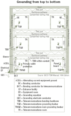
The telecommunications system's grounding (bonding) infrastructure includes the following five major components:
- Telecommunications main grounding busbar (TMGB);
- Telecommunications grounding busbar (TGB);
- Telecommunications bonding backbone (TBB);
- Grounding equalizer (GE);
- Bonding conductor for telecommunications (BCT).
The TMGB is the central attachment point for all components of the telecommunications system's grounding (bonding) infrastructure. Located in the telecommunications entrance facility, the TMGB is a predrilled copper busbar with holes for use with standard-sized lugs. The standard requires the TMGB to be a minimum of 6.3-mm (0.25-in.) thick by 100-mm (4-in.) wide and variable in length.
The TGB is the attachment point for all telecommunications systems and equipment in a specific telecommunications space. Therefore, each telecommunications space throughout the building should have a TGB. Also a predrilled copper busbar with holes for standard-sized lugs, the TGB must be at least 6.3-mm (0.25-in.) thick by 50-mm wide (2-in.). The TMGB and TGBs must be insulated to ensure they are electrically isolated from the wall or other mounting surface.

The TBB is a 6 AWG or larger grounding (bonding) conductor that bonds all TGBs with the TMGB as part of the telecommunications pathways and spaces (independent of cable). The size of the TBB is dependent on the length, up to a maximum size of 3/0 AWG for lengths greater than 20 meters (66 feet).
"Many people don't size the TBB correctly," says Withey. "It's important to follow the table in the 607-A standard because sizing the TBB too small will prevent it from adequately carrying voltage. Installers should also be aware of the bend radius and separation requirements of grounding (bonding) conductors as specified in the standard."
Whenever two or more TBBs exist in a multistory building, they must be bonded together with a GE at the top floor and at every third floor in between. The GE is also sized the same as the TBB. "If there's a failure in one TBB going down to the TMGB, having a GE every third floor provides redundancy for the voltage to travel across and down the other TBB," says Withey. "The standards thoroughly encourage redundancy when it comes to bonding." J-STD-607-A also recommends that each TGB be bonded to the building's structural steel for additional redundancy.
From the telecommunications entrance facility, the TMGB is bonded to the building's grounding electrode system with the BCT. The BCT is also sized like the TBB and GE at a minimum of 6 AWG. The NEC requires an intersystem grounding (bonding) connection accessible at the electrical service equipment. This is considered the best location for grounding (bonding) the telecommunications system to the building's grounding electrode system.
Tools and techniques
Although the telecommunications system's grounding (bonding) infrastructure seems straightforward, there is still confusion about what must be bonded and how to correctly bond to the TGBs and TMGB in the telecommunications spaces. Various grounding and bonding solutions are available from a variety of manufacturers to help ensure proper bonding in telecommunications spaces.
"To determine what should be bonded, installers need to ask themselves if a metallic component is attached to the data communications cabling infrastructure, or in contact with another metallic component attached to the infrastructure," explains Withey. "Any metallic component that is part of the data communications infrastructure must be bonded, and that includes racks, ladders, enclosures, equipment, surge protection devices, and cable trays."
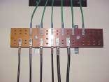
Grounding products and solutions include busbars, insulation products, ground straps, conductors, compression lugs, and tools. Horizontal rack busbars and vertical rack busbars help provide an electrical continuity path between equipment.
"Rack busbars allow you to bond individual equipment per manufacturers' specifications and then bond the rack busbar to the TGB," explains Withey. "These products act as a consolidation point for bonding, and they are based on the idea that if there's an easy location for bonding, installers and end users will be more apt to do it."
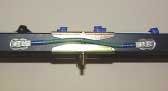
Ground straps provide a grounding (bonding) pathway between metallic components, such as cable runway lengths. In each telecommunications space, metallic components are bonded to the TGB with a grounding (bonding) conductor—preferably using two-hole lugs, which offers a more secure connection than one-hole lugs that can loosen if jarred. The Code requires all clamp and compression connections to be UL 486A-listed.
A compression tool is used for terminating the grounding (bonding) conductor to the lug, and antioxidant joint compound is used to improve the electrical conductivity and enhance the connection. "Poor bonding connections is a common problem, either due to improper compression or not cleaning the surface properly," says Withey. "It's imperative to scrape the connection location to remove any paint, enamel, lacquer, or other nonconductive coating, and then use the antioxidant to reduce corrosion that increases resistance."
An exothermically welded connection is another method of bonding that is considered a better connection; however, grounding (bonding) with compression lugs is preferred in many instances to facilitate moves, adds, and changes. "Exothermic welds are typically used for grounding (bonding) the TGB to the TBB, because it's not a connection that will need to be moved," says Withey.
Risk reality
Avoiding potential differences via bonding is key to preventing safety hazards and damage to your customers' investment that can cause costly downtime. With more intelligence being packed into single chips, today's networking equipment circuitry requires decreased voltage levels, making equipment much more susceptible to damage. When voltage specifications are exceeded, contacts, tracks, or semiconductors of printed circuit boards can overheat or melt, causing immediate damage to or degrading of the equipment over time, depending on the amount and duration of current.
"It's like stacking 25 books on a shelf, and one day you come in and the shelf has failed and the books are on the floor," says Withey. "Some might think that no damage was caused from the previous night's lightning storm just because they don't see it."
Bonding, however, is still not being done for many installations, and the differences in potential create a safety issue and equipment degradation. "Bonding is a sizeable job, and I've had many installers tell me that when they show their customers the cost of bonding, the customer isn't willing to pay for it," says Withey. "It's not unusual to walk into a telecommunications room and see no sign of bonding, even at those customers whose entire business relies on their communications system."
But implementing proper primary surge protection at the cable entrance protects the telecommunications system from overvoltage that may enter from outside cables. Secondary surge protection is an additional level of protection for diverting small currents and transient surges away from equipment.
"Bonding is separate from power protection, and primary and secondary protection should still be used as required by the codes," says Withey. "It's the combination of power protection and proper bonding that will save the customer's investment."
Betsy Ziobron is a freelance writer covering the cabling industry, and a regular contributor to Cabling Installation & Maintenance. She can be reached at: [email protected]

