Workmanship in Category 5 installations
William J. Garver
AMP Inc.
It has been stated over and over again that workmanship during installation affects the performance of high-performance data cabling, especially Category 5 cabling. But, it has remained unclear as to which workmanship practices are most detrimental, and how much such practice affects a given cable run. How robust are Category 5 systems?
From a manufacturer`s viewpoint, it is essential that systems be tested to failure so sufficient safety margin can be designed into the components to compensate for various workmanship factors. A difficult question to answer is how much safety factor or margin is sufficient to ensure consistent performance to the Electronic Industries Association/Telecommunications Industry Association-568 specifications, particularly for near-end crosstalk.
During laboratory testing, we found that some conditions are much worse than others. We wanted to identify these conditions and establish their magnitude, both as individual effects on the channel and in combination as a series of accumulated factors. All these conditions were benchmarked against a channel ideally installed in a laboratory using well-trained technicians.
The individual test conditions and their rationale are as follows:
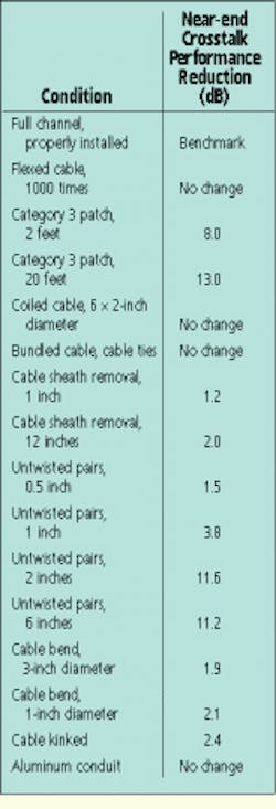
- Benchmark channel consisting of 90 meters of horizontal cable, terminated at each end and installed with 2-foot drop, patch and equipment cables, as defined in the proposed TSB-67 channel specification.
- Flex the drop cable 1000 times to simulate station-end abuse.
- Replace 2-foot Category 5 patch cable with a Category 3 cable, both 2 and 20 feet long, to simulate installer error when changing patch locations.
- Coil horizontal cable six times around a 2-inch-diameter plastic rod, 6 inches from the station end, to simulate extra cable stuffed into an outlet box.
- Apply three cable ties, spaced 6 inches apart, at a distance of 10 meters from the station end. Apply 20 pounds of force to each tie around a bundle of six cables.
- Remove outer cable jacket at the station end, 1 inch and 12 inches long.
- Untwist cable pairs at the termination point at these lengths--0.5 and 1 inch, 2 and 6 inches.
- Ten meters from the station end, bend horizontal cable 360 degrees around a 3- and 1-inch diameter pipe. Make a tight kink in the cable.
- Place horizontal cable through a 30-meter section of aluminum conduit.
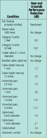
The test results show that cable untwist at the termination points and replacement of the Category 5 patch cable with lower-grade Category 3 cable are most detrimental to the performance of the channel. Other conditions, such as cable flexing, coiling, bundling, sheath removal, 360-degree bends and placement in a conduit, had minimal or no effects on the channel.
Cumulative problems
Another concern evaluated in the laboratory was that the accumulated effects of a series of conditions might adversely impact the channel. These conditions were sequentially added to the system, while maintaining the previous conditions. It was expected that the near-end crosstalk performance in such a situation would progressively worsen.
Also, some conditions were applied at both the station and equipment ends, and readings were taken from both ends to see if they were the same.
The readings from the station end exhibited progressive deterioration, as expected. However, the measured values from the equipment end did not follow the same pattern. A possible explanation for this is that all of the workmanship variables were placed at the station end while only half were installed at the equipment end, creating less impact on the channel readings from that point.
It was also observed that on channels that have a horizontal cable length of less than 30 meters, the network analyzer picks up additional effects from far-end connectors and cords that would not normally be observed in channels with longer runs. Although these effects are still being evaluated, lengths shorter than 10 meters may require additional margin to ensure compliance to EIA/TIA specifications.
These test results provide some indication of the amount of margin that needs to be provided for installed systems to ensure consistent compliance with the proposed EIA/TIA channel performance requirements. With the exception of mismatched patch, drop or equipment cords, the margins are achievable in a well-designed Category 5 cabling system. q
William J. Garver is a director of development engineering at AMP Inc., Harrisburg, PA.

