Fiber's future requires clarifying test methods
Two tiers of fiber testing may soon help simplify specification for both designers and installers.
So, what superhighway does your cabling seem to be headed onto these days?
According to a recent BICSI (www.bisci.org) survey, fiber use is clearly on the rise. Results of the survey, sent late last year to more than 10,000 BICSI members worldwide, show a high interest for 100/1,000 Ethernet, and indicate that most respondents are confident that their applications will run after testing.
But overwhelmingly, survey respondents felt that clarifying the current fiber test methods would be beneficial.
What's being installed
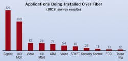
Applications abound on fiber cabling, as shown in the results in the figure above. Naturally, every building and campus has multiple applications running on its fiber networks. Not surprisingly, then, survey results showed that 38% of fiber installations are for gigabit applications. For 100 Mbit/sec applications, the percentage reduced to 27% while video and 10 Mbit/sec applications came in next with 7% each. It should comes as no surprise that, according to survey results, Ethernet is the prominent delivery protocol for data systems, with token ring and FDDI less common.
Without question, there is significant interest in 850 nm 100/1,000 Ethernet that can auto-negotiate to switch up to or down over longer distances than what is achievable by copper cabling. In fact, 89% of those responding to the survey said their customers would be interested in this technology. (See sidebar, "What is auto-negotiating, anyway?", page xx.)
An auto-negotiating 100/1,000 Ethernet technology conceivably would let backbones switch between 100 Mbits/sec and 1,000 Mbits/sec data rates, should an increase or decrease in attenuation be induced into the system (for example, when a technician may be working on a cable). In this way, the backbone would stay alive should the attenuation increase above that allowed for Gigabit Ethernet.

The TIA Fiber Optics Subcommittee FO-2.2 reviewed the survey results at its January meeting and has established a study group to determine manufacturer interest and product development feasibility for auto-negotiating 100/1,000 Ethernet. The study group is led by John Struhar of OFS ([email protected]).
But with Gigabit Ethernet on the rise, many wonder about the tight cabling loss budgets, such as 2.38 dB on 62.5-µm fiber specified by IEEE 802.3, and also about the limited distance support. This one concern alone has caused questions to be raised in the BICSI survey regarding a fiber-based Ethernet auto-negotiation standard, and the certification testing to ensure that the cabling is installed and working properly.
Loss testing considerations
Optical-fiber networks are specified to operate over a range of optical power levels at the receiver. Naturally, these levels are affected by loss in the fiber cabling, including the cable, connections and splices. The allowable "channel insertion loss" termed in the IEEE 802.3 standard is more commonly known as the "loss budget" in cabling vernacular.
As an example, the cabling loss budget for 1,000Base-SX is specified in IEEE 802.3 to be 2.38 dB for 62.5-µm cabling. Cabling losses above this threshold will cause insufficient power level at the receiver-thereby, a non-working system. (Excessive cable lengths will also affect a working versus non-working system.)
There are several causes for loss in an optical-fiber cabling system, including stresses placed on the cable, dirty connectors, and the installation techniques used in terminating connectors. In some instances, even the movement of the optical-fiber cable and connectors will affect loss.
For example, moving connectors in the back of a patch panel when trying to remove a connector to look at its end-face may cause a severe bend in the fiber if it is not carefully returned to its managements system. One way to identify the location of these bending losses is by using a high-power laser visual fault locator (VFL). When the VFL is placed on a fiber with excessive attenuation, the fiber will glow at the point of trouble.
Dirt-even microscopic dust particles-is yet another enemy of connectors, and shown to be a leading cause of fiber failure. Once a dirty connector is mated to another connector, both become dirty. One way to ensure a clean connector is to use a video microscope with a 400x magnification. Always remember that when testing optical-fiber cable, make sure that the test cord connectors are clean and that they match the fiber type you are testing (e.g., 50/125 µm to 50/125 µm), otherwise, a mismatch (e.g., 50/125 µm to 62.5/125 µm) can cause readings that are significantly high-in the order of 4 to 5 dB.
Today's favored test instruments
The BICSI survey indicates that the most popular of test instruments used in optical-fiber testing are the optical loss test set (OLTS) and the optical time domain reflectometer (OTDR). In addition, several respondents said they are using VFLs, which are generally used to identify fiber polarity, breaks, and high sources of attenuation (such as an extremely tight fiber bend in a patch panel). Some VFLs are now being produced with two light sources-one constant and the other oscillating-to help verify fiber polarity.
When testing fiber cabling, most survey respondents (71%) said they are using an OLTS (power meter with light source), and in many cases (55%), an OTDR. From this data, it is evident that many fiber installations are being tested with both instruments.
Testing of premises optical-fiber cabling is still simple and straightforward, with the primary criteria being loss and fiber length. Sixty percent of the respondents said they are confident that their applications will work after performing the tests; however, 82% say they want clarification of what and how to test their cabling.
The question is, "What is the appropriate way to clarify fiber cabling field-testing?"
Addressing a testing shortfall
Results of the BICSI survey were not only reviewed at the February TIA TR-42.8 meeting-they were dissected. Survey results clearly indicate that the industry needs assurance that current testing is adequate, and also needs guidance on how to perform these tests in the real world, using common test equipment.
One recognized problem is that there are numerous standards that specify test criteria. Further, designers and specifiers mostly work from experience rather than from a specific reference. Although this may seem odd, survey results showed that there is no one document that provides direction on fiber cabling field-testing, let alone how to perform the testing correctly.
In view of these results, TR-42.8 agreed to initiate a project for a Telecommunications System Bulletin (TSB) to address this shortfall. The project is entitled "Additional Guidelines for Field-Testing Length, Loss and Polarity of Optical Fiber Cabling System." It will complement other premises wiring standards, such as ANSI/TIA/EIA-568-B.1.
The scope of the TSB project will describe field-testing of length, optical loss, and polarity in optical-fiber cabling using OLTS, OTDR and VFLs. Designers will likely use the TSB to specify test requirements for a cabling project, and installers will likely use it for instruction on how to perform the tests.
With work in progress, TR-42.8 chair Herb Congdon is planning to send a draft to committee ballot in June, with publication of the TSB possibly in the fourth quarter of this year.
Two certification tiers?
In specifying the use of test instruments, the TSB could conceivably call out two tiers of certification testing for simplicity of specification by the designer and use by the installer. For example, a "tier 1" test may include the most basic optical-fiber measurement of received optical power measured by an OLTS with data capture and report generation, and assurance of fiber polarity (which may be done with a VFL). A "tier 2" test may include the requirements of "tier 1" and an OTDR trace, which will visually locate bad connectors, splices, and harsh cable bends incurred during cable installation.
Naturally, each test method would also be explained for ease of use by the installer. In this way, the end-user is not only sure that they are within the loss budget of the application, but they are also confident in a quality installation and about paying for the specified project.
The OLTS and OTDR are complimentary in testing optical-fiber premises networks. The OLTS will most closely emulate the system to be tested, while the OTDR works indirectly to characterize the installed cabling channel. These attributes make the OLTS and the OTDR ideal test instruments for full certification and commissioning criteria of installed cabling.
Bob Jensen, RCDD, is an optical-fiber programs manager with Fluke Networks (www.flukenetworks.com)
Safety tip...
When using a microscope for viewing fiber end-faces, make sure you're using one that has laser safety filters to prevent infrared light in live fibers from reaching your eyes.
How the survey was conducted
BICSI was asked by the TIA Fiber Optics Subcommittee FO-2.2 to distribute a survey to gauge whether there is an interest in developing standards for 100/1,000 auto-negotiating Ethernet operating at a low-cost 850-nm technology. Some of the impetus behind the research came from the TIA Fiber Optic LAN Section (FOLS), which has seen success with products being deployed after the recently published 10/100 Ethernet standard.
Simultaneous to the subcommittee's request, BICSI was asked by TIA TR-42.8 to distribute a survey on the suitability and sufficiency of current optical-fiber testing practices. BICSI's standards committee deemed both subjects important to the industry and authorized distribution of a combined survey.
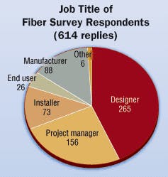
The survey was distributed in late September 2001 to 10,000 BICSI members worldwide, with 614 valid surveys completed and returned at the end of October.
What is auto-negotiation, anyway?
Introduced in 1995 as an optional function of the IEEE 802.3u Fast Ethernet standard for 10 and 100 Mbits/sec twisted-pair media, auto-negotiation is a process that lets devices-hubs, switches, network cards, etc.-with different technologies communicate and exchange information over a link about their speed and other abilities, so that they can interoperate. For instance, the protocol means that each port on a switch can automatically adjust to the operating speed and duplex mode of a network card.
For optical-fiber cabling, only the 1,000 Mbits/sec 1,000Base-X technology includes auto-negotiation capabilities that can link devices on a Gigabit Ethernet fiber link for determining support and configuration for common modes of operation. (No auto-negotiation system will work across the two Ethernet standards of 100 and 1,000 Mbits/sec because each uses different sources for optical signaling.)
Auto-negotiation allows for easy transition from 10 Mbits/sec shared Ethernet to the higher bandwidth 100 Mbits/sec full-duplex Fast Ethernet. It automatically senses a port's duplex mode, permitting devices to both configure the speed and change, for example, to full-duplex for higher throughput. Auto-negotiation also enables an automatic configuration to provide the best mode of operation over the link, and offers speed-matching for multi-speed Ethernet devices at each end of a link so that they can operate at the highest speed offered by a switched port.

