Design your network to achieve electromagnetic compatibility
Electromagnetic compatibility is achieved by reducing emission levels, interrupting the transmission path, or protecting the "victim" from emissions.
Jim Romlein, MIS Labs
When designing and installing in the telecommunications infrastructure, it is important to know what causes electromagnetic interference or radio-frequency interference (EMI, RFI) so that you can achieve electro- magnetic compatibility (EMC) in your network. In addition, you should be aware of EMC regulations as they apply to telecommunications. For example, the Telecommunications Industry Association (TIA, Arlington, VA) has published the ANSI/EIA/TIA-569 and -569A standards, and one of the TIA task groups--chaired by Donna Ballast, communications analyst at the University of Texas at Austin and author of the "Ask Donna" column--has studied some of the effects of EMI and RFI. To complete the study of EMI and RFI in a telecommunications system design, two case studies are presented describing actual problems at client sites.
A review of some fundamental definitions is necessary. EMC--the goal you want to achieve in your telecommunications system design--is a state in which all electronic systems operate harmoniously with each other. EMI and RFI are measures of emissions emanating from a device, and electromagnetic immunity, or susceptibility (EMS), is the measure of the device`s robustness and ability to operate in the hostile electromagnetic environment.
Almost every electronic device emits some electromagnetic interference. These emissions can be transmitted as electromagnetic radiation or conducted through power, network or grounding cables. At the same time, most electronic devices are susceptible to emissions generated either internally or by other devices.
In a distributed network design, three factors cause electromagnetic interference. If any of the following is absent, EMI does not occur:
A source of conducted or radiated electromagnetic noise, known as the "culprit"
A medium through which the noise is transmitted
A receptor that suffers adverse effects from receiving the conducted or radiated electromagnetic noise, known as the "victim."
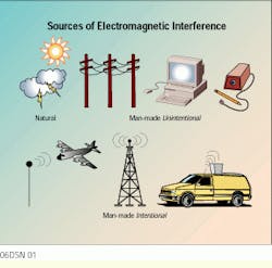
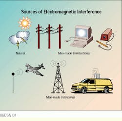
Sources of electromagnetic noise are derived from natural and man-made origins. Natural sources below 10 megahertz are dominated by the atmospheric noise generated by electrical storms. Above 10 MHz, natural sources are primarily cosmic noise and solar radiation. Man-made noise emanates from intentional and unintentional sources. Intentional sources are those that must radiate to perform their tasks, for example, AM, FM, TV, police and other broadcast transmitters, pagers, diathermy machines (used in medical and surgical applications), and mobile and cellular phones. Unintentional sources include computing devices, relays, switches, motors, tools, appliances, power lines, fluorescent lights, arc welders, auto-ignition system, cable TV and the electric pencil sharpener. With the proliferation of both intentional and unintentional sources, EMI, particularly in urban areas, has reached serious levels.
In one real, and tragic, situation, a man visited his wife in the hospital, where she was connected to monitoring equipment in the intensive care unit. While there, he decided to make a call on his cellular phone. Suddenly the "code-blue" team rushed in and performed emergency procedures on the patient. After the team left, the man decided to make another call. Again, the code-blue team rushed in but, unfortunately, this time the man`s wife did not survive.
Receptors susceptible to EMI include communications receivers, such as radio and television, radar and navigation devices; computing devices and ordnance (weapons, ammunition and explosives). The effect of the interference on the victim receptor depends on the strength of the source, transmission medium, distance from the source, coupling mechanisms and degree of susceptibility.
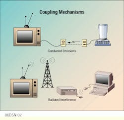
Coupling mechanisms between culprits and victims are varied and complex; however, by separating the devices into three basic components--antenna, box and wire--the primary mechanisms can be understood. Conducted emissions, which are of most importance to installers, may be coupled via power utilities, common grounds or interconnecting cables. For radiated interference, the most common coupling paths are antenna-to-antenna, antenna-to-wire and wire-to-wire. Box-to-box coupling usually is not the most important path, except when low-frequency magnetic fields are involved.
Disruption in detection of transmitted intelligence occurs when the noise-frequency spectrum of the interfering source (or culprit) significantly overlays the frequency spectrum of the receiver (or receptor) side--also known as band noise. For the noise to be significant, it must exceed the noise-reject capability of the receiving side. Two conditions must, therefore, exist for a disruption to occur: there must be noise in the frequency spectrum of the receiver side, and the noise must be significant.
Low-frequency signals, such as analog telephone, are not generally affected by high-frequency interference; for example, an analog telephone in close proximity to a radio transmitter. But, if the telephone cabling is nontwisted quad wire run in parallel to the AC power lines--often the case in a home--the user will hear an AC hum on the telephone. If the hum is significant enough to annoy the user, it can also disrupt modem communications. Radio transmissions are several orders of magnitude above the frequency spectrum of the telephone (and the user), so the noise will not heard; however, the harmonics of 60 hertz are within the telephone`s frequency spectrum and will be heard.
Data communication signals are susceptible to in-band noise as well. Most local area network physical layers are baseband signals; that is, they often use the entire frequency band from almost DC to at least the third harmonic above the transmit data rate. Examples of such physical layers are EIA-232, IEEE 802.5, 10Base-T and 100Base-T. Signals such as 10Base-T are not only susceptible to 60-Hz power noises, but may also be disrupted by close proximity to band noises from AM radio signals or 1.554-megabit-per-second T1 signals, for example.
Susceptibility to these in-band noises can be lessened by reducing the antenna effect of the cabling system. Often the use of Category 5 cabling instead of Category 3, or screened twisted-pair instead of unshielded twisted-pair (UTP), will reduce the susceptibility of the cabling system to induced noises. The noise is still within the frequency spectrum of the receiver, but it is reduced by the cabling system to an insignificant level.
Installing a network
As you design a distributed network, consider the factors that need to be present for EMI to occur: a victim, a culprit that is emitting and a medium to carry the emissions.
You have no control over the victim, because networks are, by definition, developed to accommodate a variety of equipment. In most cases, you will know what types of equipment will be used. In an office network, a Class A device will be used, but in a hospital, it may not always be a Class A device attached to the network.
Culprits can be switching equipment, motors and any devices that open and close an electrical switch. You can determine the strength of the device by using simple logic: The larger the voltage and current that the device uses, the more likely that it will be on the culprit list. Generally, you will not have any choice in the selection of these culprits because they are already there at the job site.
The only thing you can control is the medium--what it is and how to place it. There are no definitive guidelines on how and where to place the cabling, but you now know what the issues are: distance from the culprit is often the best tool, followed by cable shielding. Standards are another area you should review as you design your network.
An area of concern for the installer is the separation of telecommunications pathways (and the media in the pathways) from power distribution systems. A table in section 10.3 of the TIA/EIA-569 standard specifies pathway and space separation distances from electromagnetic energy sources. In addition, a specific separation for power lines with voltages below 480V AC is defined in Table 10.4-1 of the standard. A TIA working group, headed by Ballast, was in charge of determining whether these distances and values were merited.
The working group ran several tests to determine the effects that noise sources have on UTP cabling systems. A ring waveform test and an electrical fast transient-type waveform test were run, the latter being the better model for real-life conditions. Tests were run with different output voltages, cable separations and cable terminations. Voltages were measured on the UTP cables alone, and bit-error rate test sets were used to see how data might become corrupted in the presence of high external noise sources.
The group found that the UTP cabling system was not susceptible to noise sources. As a result, the table has been dropped from the TIA/EIA-569A standard. In the draft that is now in circulation, two separation distances were kept: Install cable with 5 centimeters (2 inches) of separation from open power conductors and 120 millimeters (5 inches) from fluorescent lights. Pete Martin, operations manager at MIS Labs noted that the 120 mm does not equal 5 inches; it should read 12.7 cm (5 inches). Under Section 10.3.2 of the proposed 569-A, the working group summarizes its findings as "Generally, very little separation is needed..."
Which standards cover electromagnetic compatibility? The Federal Communications Commission (FCC) regulations, part 15 and part 18, cover a variety of products. Part 15, for example, classifies products in three general categories: intentional, incidental and unintentional radiators. An example of an unintentional radiator is information technology equipment, which includes any logic device with a clock greater than 8 kilohertz--computers, telephones, radios and recorders, for example. Unintentional radiators are divided into two more subcategories: Class A devices intended for commercial, industrial or business use, and Class B devices intended for residential environments.
As advances in digital technology push frequencies higher, the potential for undesirable emissions at higher frequencies increases. For this reason, the FCC now requires testing to 2 gigahertz if the highest frequency generated or used in the equipment under test is in the 108- to 500-MHz range, and up to 5 GHz if the device generates or uses signals in the 500- to 1000-MHz range. Some classes of products are specifically exempted from FCC part 15 regulations, however, including computing devices aboard vehicles (ships, cars and aircraft), electronic systems used by a public utility or in an industrial plant, computing devices incorporated into appliances such as dishwashers and washing machines, specialized medical equipment, and extremely low-power devices.
Testing for emissions and susceptibility
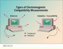
EMC measurements include tests for emissions and susceptibility (also referred to as immunity). EMI tests involve measuring the frequency and amplitude of undesirable signals emitted by the equipment, or device, under test. Signals radiated into free space are known as radiated emissions, while signals traveling along power cords or other interconnecting cables are known as conducted emissions. Spectrum analyzer-based EMI receivers are ideal for these tests.
EMS testing determines the ability of the equipment under test to operate properly in an undesirable electromagnetic, or ambient, environment. Radiated susceptibility tests use signal sources and power amplifiers to generate high-level fields around a device. Conducted susceptibility measurements are performed by coupling an offending signal of a specified level onto cable to try to induce a malfunction in the equipment under test.
Other forms of susceptibility testing include electrostatic discharge, lightning, transient burst and voltage-surge.
Because so many factors affect emissions, an environment with known characteristics must be used when measuring EMI. Testing within a known environment is critical because it lets you compare the emissions for a device measured at one facility to emissions of the same device at another facility.
Case studies
MIS Labs has conducted several tests at client sites. In the following case studies, you will see that the victim is the same but each has a different culprit. Keep in mind the issues you find when you are installing cables in a building, noting that antenna-to-cable is one of the most common coupling methods.
In a multistory commercial building that has been occupied for less than one year, the display on video monitors at various locations in the building moves to one side of the monitor. It was determined that the ground field from the nearby subway was interacting with the ground field of the building. The differences in the ground potential between areas of the building ground field caused current to flow in the steel columns of the building. Because current flow caused magnetic fields, some of the steel columns became magnetized. The problem seemed to be that high magnetic fields surround certain steel beams of the building. Thus far, no solution has been found.
In another case study, a small insurance office in a commercial multitenant building encountered a problem where video monitors became jumpy at various times of the day. The EMI spectral tests revealed that the video monitor was the biggest source of EMI in the office environment, with most of the noise between 10 kHz and 4 MHz. When the monitor was turned off, no significant noise, conducted or radiated, was detected. The power-analysis test revealed no significant high-frequency noise. The uninterruptible power supply created some low-level neutral- to-ground voltage, which was slightly higher than that on the normal power line. Instantaneous voltage measurements detected no voltage-level problems; however, problems showed up when voltages were monitored over a period of time.
Upon further testing, voltage swells were detected, with the line voltage varying from 113.5 to 134.5 volts. Upon checking the power wiring, it was determined that the AC outlet in the office panel board was found to be configured as an isolated ground branch circuit with a pass-through ground. The AC (green-wire) safety ground was extended through the serving panel board into the basement, past the service entrance, up the coal chute to an abandoned ground rod, which was not bonded to any of the building common bonding network--an extremely hazardous condition. To make a long story short, the problems were riding in on the AC power. q
Jim Romlein is president of MIS Labs, Watertown, WI, and has been nominated to the board of directors of the Telecommunications Industry Association. He is also a member of the TIA TR-41.7.2 working group on bonding and grounding.
Electromagnetic interference (EMI) can be caused by natural causes such as electrical storms, or from man-made origins, including power lines, broadcast transmitters, cellular telephones and pencil sharpeners.
Conducted emissions can be coupled through interconnected cables (top), while common coupling paths for radiated interference are antenna-to-antenna, antenna-to-wire and wire-to-wire.
Signals radiated in free space are radiated emissions, while signals traveling along interconnecting cables are known as conducted emissions.


