Do you have all the facts about time-delay skew?
Tom Debiec
Berk-Tek Inc.
In the past several months, there has been a proliferation of information concerning time-delay skew. Most of this information has been based on the need of cable and component manufacturers to market their products. The issue has also been sensationalized in recent months in various cabling publications.
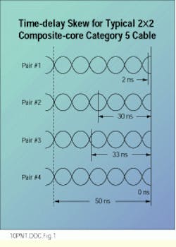
In an ideal situation, a signal that is sent down a cable on all four pairs at the same time will arrive at the opposite end of the cable at the same time. In order to meet the crosstalk requirements of the Ansi/tia/eia-568A standard, unshielded twisted-pair (UTP) cables are often designed using a different twist length for each pair. This difference in twist length causes the signal to arrive sooner on one pair than on another. The time difference between the arrival of the signal on the fastest and slowest pairs is referred to as time-delay skew.
The present controversy around skew concerns Category 5 plenum cables that do not have the same insulating material on every pair. In the past, Category 5 plenum cables were insulated with fluorinated ethylene propylene (FEP) on all four pairs. However, cable manufacturers were placed in a difficult position in 1995 due to an inadequate supply of FEP.
As a result of this material shortage, cable manufacturers were forced to locate insulating materials other than FEP that were capable of meeting the requirements of the UL-910 flame test that is applied to plenum cables. The result of this development has been cables with composite cores -- so-called "1 + 3" and "2 + 2" designs that substitute non-FEP insulating materials on one or two of the four pairs. The non-FEP insulating material is flame-retardant polyolefin.
Because of this use of different insulating materials, composite-core cables inherently have higher time-delay skew than a cable with the same insulating material on all pairs. This is due to the difference in dielectric constant between the insulating materials.
Some manufacturers would have you believe that skew is the only parameter dictating the performance of high-speed network cable. Category 5 cables, however, are highly engineered products that call for a delicate balance of design and manufacturing parameters in order to meet all the performance requirements set forth in industry standards. Skew is just one of the requirements that impacts a high-quality cable design. Other electrical characteristics of the cable include attenuation, impedance, near-end crosstalk and structural return loss; also under examination recently are other parameters such as cable balance and far-end crosstalk. All of these contribute to how well a system operates.
Here are a few examples of the design compromises required for a robust Category 5 cable design:
- Changing the rate of twist of a pair in order to improve skew may adversely affect the crosstalk performance of the cable.
- Due to the high cost of plenum insulating materials, some manufacturers insulate the individual wires with only enough FEP to yield minimum acceptable impedance.
- Cables designed around the TIA minimum impedance requirements yield products with marginal attenuation and poor return loss characteristics.
The migration of existing networks up to and beyond 100 Mbits/sec is a concern for network managers. In the past year, new 100-Mbit/sec applications have emerged that use more than two pairs of a four-pair cable for data transmission. For example, specifications for 100VG-AnyLAN (proposed by the Ieee 802.12 committee) and 100Base-T4 (proposed by the Ieee 802.3 committee) were released in late 1995.
Both these standards are designed to operate over Category 3, 4 and 5 wiring. Data transmission at 100 Mbits/sec is accomplished by splitting the 100-Mbit/sec data stream into multiple lower-speed data streams. In the case of 100Base-T4, three pairs are used to transmit data, with the remaining pair used for collision detection. It is critical that the signals arrive at the opposite end of the cable at approximately the same time so they can be successfully recombined by the receiver. The time-delay skew requirement for 100VG-AnyLAN is 67 ns per 100 m of transmission distance, and the requirement for 100Base-T4 is 50 ns per 100m.
Other 100-Mbit/sec applications, such as Fiber Distributed Data Interface (governed by the Ansi X3T12 committee), 100Base-Tx (Ieee 802.3 committee) and even Asynchronous Transfer Mode (ATM) at 155 Mbits/sec, use only two pairs in the cable. One pair transmits the signal and the other pair receives it. Pair-to-pair skew is not a specification of any of these standards.
Requirements regarding skew are also not part of the Ansi/tia/eia-568A commercial building wiring standard. The TIA has drafted PN-3772, "Propagation Delay and Delay Skew Specifications for 100-ohm, 4-pair Cabling," a document that addresses the issue. The limits set forth in it are based on the requirements of 100Base-T4, and the maximum skew has been set at 50 ns per 100 m. The document will be issued as a Telecommunications Systems Bulletin (TSB), which is currently being balloted.
PN-3772 makes a number of assumptions. The first is that plugs and hardware have no adverse effect on the delay skew. Second, it is assumed that jumpers are the same length for different pairs in the link, and third, that the installation does not affect the skew. These assumptions are currently under study by the TIA working group.
The test procedure outlined in PN-3772 is designed for use in a laboratory environment, and requires the use of a vector network analyzer. In the case of Category 5 cable, delay skew must be sweep-tested between the frequencies of 1 and 100 MHz. In addition, the skew may not change more than plus or minus10% due to temperature variation. The environmental compatibility requirement ranges in temperature from 20 to 60C. The proposed TSB does not address the measurement of skew in installed links.
In a cable, skew varies proportionally in relation to length. If a cable has a length of 25 meters and the cable skew is 35 ns per 100 m, the skew for a 25-m cable would equal 8.8 ns.
Testing was recently performed to explore the effects of connecting hardware and patch cables on time-delay skew. The preliminary data shows that the effect of connection hardware on skew is minimal and that variation in skew performance between hardware manufacturers is also minimal.
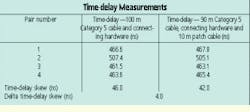
Contrary to popular belief, the addition of patch cables to a link does not increase the total amount of skew in the channel. The table shows skew test results for a 100-meter length of terminated, composite-core, Category 5 cable. It also shows the results for the same cable when shortened to 90 m, reterminated and evaluated with the addition of 10 m of patch cord. The cable used in the test was chosen because it exhibited skew close to the specification limit, so this can be considered a worst-case link.
Testing was performed in accordance with the D-4566 standard of the American Society for Testing and Materials (Philadelphia, PA) and with PN-3772, at room temperature and using the newly developed modal-decomposition method of analysis. Modal decomposition eliminates the need for baluns in the test set-up. Baluns, or impedance-matching balancing transformers, have been the weak link in the evaluation of high-frequency characteristics of cabling for some time. The elimination of baluns improves the accuracy of the test measurement at these higher frequencies.
The tabular data shows that patch cables have no adverse effects on the time-delay skew of the channel. In this example, the skew was improved by 4.0 ns. The total channel skew is a composite of the cable skew, skew contributed by termination hardware, and the patch cable. The skew contributed by cabling is reduced due to the decrease in the length of the horizontal cabling. Since time- delay skew is proportional to the length of the cable, the shorter the cable length, the lower the skew.
The patch cable has an averaging effect on the total skew. The main cause of skew in patch cables is the twist rate of a pair. Since the rate of twist of patch- cable pairs and horizontal cable pairs is not matched for each pair color, the patch cable will add to the total time delay of some pairs and subtract it from other pairs. In many instances, this results in a reduction in the overall skew.
Industry experts at the TIA have determined that total link skew of 50 ns per 100 m will guarantee successful operation of networks that utilize more than two pairs for data transmission. Standardization of this value will give application developers design boundaries for use in the development of new application standards. In effect, these new applications will be designed for use over media that meet the requirements of the published standard and may already be installed in your building.
Testing shows that hardware and patch cables have little, if any, adverse effect on total skew. There is no evidence showing differences in network performance between cables insulated with all FEP and those with composite cores, because of the methods employed by computer chips to synchronize individual streams of data.
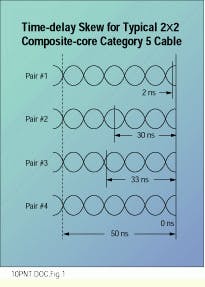
Time-delay skew in a typical Category 5 cable of 2 x 2 construction may be up to 50 ns.
Tom Debiec, registered communications distribution designer (Rcdd), is an applications engineer at Berk-Tek Inc., New Holland, PA.


