A generator-friendly uninterruptible power supply

The most favorable UPS technology combines compatibility and complete system reliability.
Many claims have been made about how one uninterruptible power supply (UPS) technology may be superior to another when it comes to generator compatibility. To understand the integrity of these claims, you need to know what characteristics are important for generator compatibility and how the various technologies operate. This will ultimately reveal the most favorable or "generator-friendly" technology-not just based on compatibility but also on complete system reliability.
Causes of generator incompatibility
The first characteristic that influences generator performance is the total harmonic distortion (THD) reflected back by the load (a UPS in this case) onto the generator. The part of the UPS that the generator sees as the load is the rectifier. Today, most UPSs use silicon controlled rectifiers (SCR) that can reflect around 40% THD on six pulse rectifiers, and 14% on 12 pulse rectifiers. This THD value is often insignificant, as most SCRs are equipped with input filters that lower the THD level to around 5%. It is only the final filtered THD level reflected onto the generator input that is a significant value.
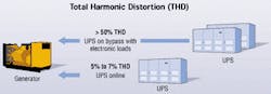
The only real effect that THD has on generators is that a load with very high distortion will require more kilowatts to power it than the same load with no distortion. Even high THD levels (50%+) are not a real threat to generator compatibility; it simply means that the generator will have to be marginally oversized to combat the higher THD. The 5% or even 10% THD that may be reflected from the input of a UPS has little or no effect on the requirement for oversizing a generator.
The input THD is not the most relevant factor in the generator- sizing equation. Instead we need to consider what will happen when the UPS transfers to bypass and the generator powers the loads directly.
As most critical loads are non-linear, such as switch mode power supplies used in computers and servers, chiller compressor motors, etc., these devices will reflect upwards of 40 to 90% THD in a typical data center. This means that the critical loads THD must be considered for generator sizing; in most cases, they will be much higher than that of the UPS modules. Even with critical load THD levels at greater than 50%, oversizing the generator by 20% is more than ample to combat the THD.
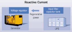
When a generator sees a heavily leading power-factor load, like a large unsaturated capacitor bank on a UPS module input filter, the capacitor bank will start to feed power back to a voltage regulator circuit on the generator. This will cause the voltage regulation system to see a much higher voltage and eventually shut the generator down due to an over voltage error. As the rectifier ramps up with the UPS load, the net power factor of the UPS begins to become less leading, and has less of an effect on the generator voltage regulation system.
The industry-wide acceptable input THD of large UPSs is between 7% to10% at nominal load, with most manufacturers offering 5% to 7% filter solutions. It is important to understand that the consequences of 5% to 7% and even 10% THD have very little effect on loads sharing the critical bus (and exposed to the distortion). When looking at the effect of THD as a pollution source, the UPS' load level (kVA) must be considered as a factor of the THD percentage. For instance, a 25% THD level at a load of 10 kW is nowhere near as bad a source of line pollution as a 15% THD level on a 100-kW load.
Reactive current
The second and most important factor influencing generator compatibility is the amount of reactive current (kVAR) generated by the UPSs and critical loads. Reactive current is created from loads with high capacitance, such as capacitor banks of UPS input filters.
When a generator sees loads with highly reactive loads (those with very leading power factors), the capacitors feed current backward to the generator. This will cause the generator's voltage regulation system to see a much higher voltage and eventually shut the generator down due to an overvoltage error.
The problem is most apparent when the UPS module is lightly loaded and the UPS power factor is the most leading. As the rectifier ramps up with UPS load, the capacitors become saturated and the UPS' net power factor becomes less leading. The less leading the power factor, the less of an effect the UPS will have on the generator voltage-regulation system.
This problem may also occur during generator start-up conditions when the UPS rectifier output is intentionally lowered to provide a lighter and more gradual load for the generator. Limiting of the rectifier current again causes the UPS load to become highly leading, recreating the conditions that lead to loss of generator voltage regulation.
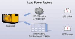
Once UPS loads exceed approximately 40%, most UPS systems will have a power factor that will be manageable for most generator sets. Even the worst leading power factor loads can be overcome with enough generator oversizing. But when it comes to large UPSs and multi-module UPS systems, greatly oversizing generators is economically impractical; other solutions must be explored.
As with THD, power factor characteristics aren't the only ones to consider for generator compatibility. The combined power factor of the critical loads and the UPS system, as well as those of the critical loads, have to be evaluated to account for the possibility of the generator directly powering the loads when operating in bypass.
Peripheral loads that are not powered by the UPS and operate directly off the utility and the generator during an outage must be taken into account. Often, these peripheral loads are inductive, like the compressor motors on a chiller system. If the loads are inductive, they will have a lagging power factor that will have a compensating effect on any reactive currents the UPS may generate at lower loads.
By calculating the UPS' and peripheral loads' net load profile, you can determine the net critical bus power factor, which will typically be a lot less leading or even lagging than the power factors of many UPS systems analyzed individually. The consequence of a less leading net system power factor is that the generator system will not need to be oversized beyond the standard margin of safety.
Just because a UPS system has a favorable power factor in all operating modes doesn't mean you can avoid some degree of generator oversizing. Oversizing may still be required to allow for powering loads like motors, and for accommodating the high inrush from transformers and electronic power supplies when the generator is powering the loads directly (UPS on bypass), or when many of the loads are permanently on the utility/generator bus.
The combined power factor of all loads sharing the utility bus form the net power factor that the generator has to power.
Solutions for compatibility
Now that you know what causes generator incompatibility (leading power factors and, to a much lesser extent, THD) you can evaluate the effectiveness of various solutions for optimizing generator/UPS compatibility.
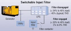
The load variable filter operates by disengaging the input filter via a contactor before generator start-up and when the UPS is lightly loaded. Disengaging the filter removes the capacitors from the line, preventing the UPS from becoming a leading power-factor load. Once the generator has walked in and is powering the UPS, the filter contactor may close only when the UPS load goes above 30% to 40%. These higher loads on the input filter are more saturated and will not create as much of a leading power factor.
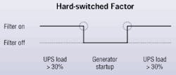
The danger with this system is that if the contactor ever fails to disengage the input filter, the UPS' reactive load characteristics will cause the generator to lose voltage regulation and go offline. Also, when the input filter is disengaged, there is no mitigation of harmonics reflected from the rectifier, which may be as high as 45%. Another unfavorable result of using this type of filter control is that every time you switch the filter, you are hard-switching a large capacitor bank inside the UPS input filter. This causes notching on the utility bus, disturbing all the loads sharing the bus-a bad effect that often can propagate to your distant neighbor's utility bus.
The choice is IGBT, but...
Since insulated-gate bipolar transistor (IGBT) rectifiers are now the component of choice for UPS inverters, the question arises, "Why aren't they more popular for UPS rectifiers?" The answer is not one of technological ability as much as it is component functionality. IGBTs can rectify AC power without creating much THD, avoiding the need for input filters and their associated capacitor banks. IGBT rectifiers can also create a stable load power factor.
The major penalty against IGBT rectifiers is lower efficiency since they switch at much higher frequencies than SCRs. The switching losses are much higher. Looking at the efficiency profile of a UPS with an IGBT rectifier, efficiency suffers as the load level decreases. This means IGBT rectifiers have severe operating cost implications, particularly with larger UPSs.
Considering that state-of-the-art, SCR-based rectifiers and input filter assemblies, such as shunt inductor filters, can offer practically identical performance characteristics (5% THD, no leading power factor / 0.95 PF)-with the added bonus of high efficiency-IGBT or power factor-corrected rectifiers offer little advantage over modern rectifiers in high-kVA UPS applications.
Line-interactive UPSs (sometimes sold under the name "on-line") may claim to be very generator-compatible but have some serious shortfalls. The basic theory of operation of a line-interactive UPS is that under stable utility conditions (V is ±10% to 15%), utility power simply passes right through the UPS to the critical load. At the same time, voltage and harmonics are regulated by a parallel current that is injected into the output.
Since the input and output are on the same bus, the parallel current being used to control the harmonics and voltage also creates a stable power factor and relatively low harmonics on the UPS input. This results in a compatible load profile for the generator.
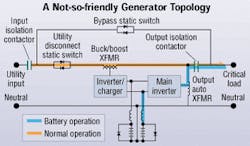
Unfortunately, the Achilles heel for line-interactive UPSs is that that they do not have frequency regulation unless they switch to battery mode (generating 100% of the output from the inverter of the UPS, which is powered by the battery bank). The problem occurs when the UPS is on generator, which hits a block load (i.e., a chiller motor starts, or there is inrush from a transformer). When this occurs, the generator frequency will typically drop. Since the UPS has no way to regulate the output frequency, it must let the output frequency drop to the generator's frequency, or switch to battery mode and let the inverter generate the output power.
If the UPS is heavily loaded in relation to the generator size, it will take the load off the generator when it switches to battery mode. The generator will then stabilize the frequency, causing the UPS to switch back to generator power, block- loading the generator. The UPS will go back to battery mode in an uncontrollable cycle until the batteries are dead, eventually causing the UPS to drop the load.
Some manufacturers have attempted to remedy this cycling by programming the UPS not to switch to battery unless the frequency drops 4 to 6 Hz below nominal. The downside is that the UPS will feed the critical load with power that may be 4 to 6 Hz out of tolerance. While this method may work unless the generator is substantially oversized, it is possible that a block may still force the UPS to battery mode since deviations greater than 4 to 6 Hz are likely. This means that line-interactive UPSs may not be free from significant oversizing requirements in mission-critical applications.
Low-kVAR input filters
A more effective input filter design that is used to optimize UPS generator compatibility is the low-kVAR filter. It is designed to filter capacitance and thus limit the reactive current for the generator to manageable levels. The consequence of reducing the capacitance is only a slight increase of a few percent in THD (typically, 6% to 7%). The extra few percent of current distortion experienced with this filter has no effect on generator output-sizing requirements, nor is it large enough to be a disturbance to neighboring loads. It's a preferred solution because it is passive and solid-state with no switching involved.
For situations demanding a very low input THD (5%) and absolutely no leading power/reactive current factor under all load conditions, MGE (www.mgeups.com) has developed a shunt inductor filter. The technology uses compensating inductors in line with the input filter capacitors. Inductor assemblies are carefully tuned to provide enough inductance to cancel the capacitance (reactive current) of the input filter capacitors.
This inductive compensation ensures that the UPS will never become a leading power factor load (generate significant reactive current), even when the UPS has no load or during generator walk-in. The shunt inductor filter is a reliable, 100% solid-state solution using only passive inductive components.
Because the shunt inductor limits THD to around 5% and eliminates reactive currents, it can theoretically permit UPS-to-generator ratios as low as 1:1 (providing allowances are made for the UPS battery-charging current and load characteristics when it is on bypass).
Well-designed input filters are tuned to filter-specific current harmonics, and only have a marginal effect on system efficiency consuming around 0.5% of the total load power. Compared to the alternative technology of power-factor corrected rectifiers, input filters offer a huge efficiency advantage.
Alan Katz is a product manager at MGE UPS Systems, (www.mgeups.com), Costa Mesa, CA.

