Testing readiness of systems with 50- and 62.5-micron fiber
Using appropriate equipment is critical to determining your multimode fiber's capabilities.
Increasingly, cabling system designers and end users are specifying 50/125-micron optical fiber into their networks. 50-micron optical fiber is not a new technology. Rather, it has been used extensively outside of North America, including Europe and Japan. The 50-micron optical fiber cable, as specified in the ANSI-approved TIA/EIA-568B.3 standard, offers more than three times the bandwidth of the standard 62.5/125-micron optical fiber in the short-wavelength window of 850 nanometers (nm; 500 MHz.km to 62.5/125's 160 MHz.km).
The short wavelength is crucial to networks, because low-cost 850-nm vertical-cavity surface-emitting laser (VCSEL) sources are being deployed to support Gigabit Ethernet applications throughout premises networks. Characterizing these optical fibers with the right equipment and methods is extremely important to ensure a network's cabling performance. When testing the optical-fiber cable for Gigabit Ethernet networks, Fluke Networks recommends that you use a tester equipped with a VCSEL source at 850 nm and a laser source at 1,310 nm.
When testing for light-emitting-diode (LED) systems, such as 10Base-FL and 100Base-FX, we recommend that you use a tester equipped with LED sources of 850 and 1,300 nm.
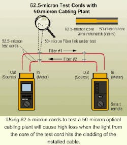
Most importantly, when preparing to test the cabling, ensure that the size of the optical fiber within the test cords matches the size of the fiber within the cable. For example, if the installed cabling is 50-micron optical fiber, use test cords with 50-micron fiber. With this equipment readily available, you will be on your way to ensuring that you are getting the most accurate test results possible.
Measuring loss
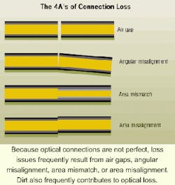
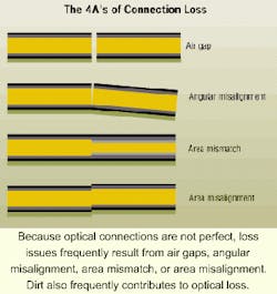
Losses in optical-fiber cabling are measured in decibels (dB). Loss is a result of the inherent makeup of the fiber, as evidenced by the medium's loss-per-kilometer specification (dB/km), cable-placement issues such as tight bending, and connection points. Losses at connection points are generally due to dirt and/or a combination of any one or more of the four A's: air gap, angular misalignment, area mismatch of cores, and axial alignment mismatch.
Generally, with premises cabling, connection points are the biggest contributors to cabling loss. And that is why the optical-fiber cabling should be tested using ANSI-approved TIA/EIA-526-14-A, Method B. Testing according to Method B results in a complete loss measurement of the cabling by including the near-end and far-end connection losses, as well as everything in between.
Fiber mismatch
Connecting 62.5- and 50-micron fiber when testing cabling is a common error, and it is also a cause of significant mismatch of connections. One reason that technicians frequently make this error is that there is no identification scheme, such as color-coding, that is specified to distinguish the two types of cable or connectors. In addition, especially in areas that use 62.5-micron optical-fiber cabling and are migrating to 50-micron cabling, this fiber mismatch possibility is not a primary concern of the installer or project manager.
To explore the results of fiber mismatch, let's examine a scenario in which you connect the wrong-sized test cord to the cabling, and you are testing with an LED source. Let's assume you are testing a 50-micron optical-fiber cabling plant for 100Base-FX and you have mistakenly picked up 62.5-micron test cords. Unknowingly, you have a mismatch of the fiber cores at the connection of the source test cord and the cabling. When launching light into the cabling, a significant amount of that light is lost as it hits the fiber cladding, resulting in loss.
This situation is analogous to a copper-cabling situation in which you connect a Category 3 patch cord to Category 5 cabling. The result for this copper channel is that it will not perform to Category 5 specifications. In the mismatched fiber scenario, the increased loss resulting from the use of inappropriate test cords is 4.7 dB.
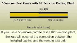
Now let's examine a scenario in which you are testing a 62.5-micron cabling plant with an LED source, and you mistakenly use 50-micron test cords. In this situation, you will not have the loss impact at the connection between the source test cord and the cabling that you had in the first scenario. Loss, however, will show up at the far end, where the tester's cord is connected to the cabling. Once again, as a result of mismatched fiber cores, you will find the loss values increased about 4.7 dB.
LED vs. laser testing
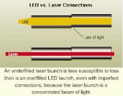
Testing optical fiber for gigabit-speed performance with laser sources will yield less loss than testing the same system for gigabit-speed performance with LED-based sources. The primary reason is that the LED uses what is called an overfilled launch-where the beam of light from the LED source overencompasses the fiber core.
It is analogous to using a search light to point out a star in the evening sky. The overfilled launch fills the fiber core with light energy having more high-order modes than that of a laser. The high-order modes travel longer distances in the fiber core, so they are more likely to suffer attenuation. Coupled with this inherent high-order mode loss is the loss caused by the connections. With a light-filled core, area misaligned connections are susceptible to higher losses, whereas an underfilled launch is less susceptible.
An underfilled launch, such as that deployed by a VCSEL, is a concentrated beam of light that is less susceptible to losses caused by high-order modes and misaligned connectors.
Comparing the two launch types, you will find that if you test the cabling with an LED source, you will end up with higher-than-expected losses if you are testing to determine the cable's ability to support Gigabit Ethernet.
Loss budgets specified for multimode optical-fiber Gigabit Ethernet applications are more stringent than those of older technologies such as 10Base-FL and 10Base-FX. These values are listed in TIA/EIA-568B.1's Table E-1. Not only are these Gigabit Ethernet standards calling for more stringent loss requirements, but they also diminish the overall cabling length for Gigabit Ethernet support. For instance, standard 62.5-micron fiber with a bandwidth of 160 MHz.km at the 850-nm operating wavelength will support 1000Base-SX to 220 meters (720 feet) with a cabling loss of 3.2 dB. On the other hand, standard 50-micron fiber with a bandwidth of 500 MHz.km at the same 850-nm operating wavelength will support 1000Base-SX to 550 meters (1,804 feet) with a cabling loss of 3.9 dB.
Testing your cabling to the right application with its corresponding source is critical to understanding its capability. Testing with a meter that contains a VCSEL source will ensure the correct measurements are evaluated for deploying Gigabit Ethernet. On the other hand, testing with a meter containing an LED source for technologies such as 10Base-FL and 100Base-FX will ensure your measurements take into consideration high-order modes and connector losses.
Bob Jensen is fiber-optic market manager with Fluke Networks (www.flukenetworks.com).
Testing Tip #1: Using the right testing method
TIA/EIA-526-14A specifies two methods of testing: Method A and Method B.
Long-haul access providers historically have used Method A because for them, more loss is found in the cable than in the connections. Method B is used for premises applications, and includes the connections on the near and far ends of the cabling. Method B is also specified in the TIA/EIA-568B.1 standard, which recently was approved by ANSI.
To remember which method is appropriate for which user, relate Method A to "Access provider" and Method B to "Buildings."
Testing Tip #2: Cleanliness is next to Godliness
Before testing any fiber-optic cabling, ensure that the connections are clean by wiping them with lint-free wipes or swabs moistened with 95% isopropyl alcohol. Protect all connectors with dust caps when the connectors are not in use.
Testing Tip #3: Recognizing a mismatch
If you are using an LED source and expect to see a loss reading of about 1.7 dB for a link, but find that your test results yield a 5- to 6-dB loss, you may have fiber mismatch between your test cords and the cabling. If you check and it is not a mismatch, it may be time to bring out an optical time-domain reflectometer.
Testing Tip #4: Cutting your losses
A cabling channel that includes several area mismatches of 62.5-micron and 50-micron fiber in a channel still will exhibit losses of approximately 4.7 dB. That roughly 4.7-dB loss figure does not multiply as the number of mismatches does.
So, if you have corrected one mismatch and the loss results have not improved, look for another mismatch.
