High-performance patch cords no longer a weak link
In the age of matched system components, patch cords are tightly controlled, and tightly bent too.
For a long time, many in the cabling industry have viewed patch cords as the proverbial wild card in end-to-end systems. Engineering types are quick to point out that in these products, you have two 8-pin modular plugs attached to the ends of a rather short length of cable. The electrical phenomena going on inside can be frightening. When two plug-jack connections, with all their associated crosstalk and return loss, are separated by so little cable, the undesirable effects from each connection can run into each other.
Users of cabling systems may also approach the issue of patch cords with dread, particularly if the components have been treated as an afterthought. And that is not uncommon. In many cases, installation organizations have installed and certified horizontal cabling systems in what has been known as the basic-link setup, which excludes patch cords. Once the installer has come and gone, the end-user must complete the system, using patch cords to connect users' workstations to the network. Sometimes, the patch cords are not specified in the project, so their installation becomes patchwork-done at the last minute.
"Patch cords are an important link, but they can be somewhat forgotten," says Gary Bernstein, director of product marketing for the telecom market with HellermannTyton (www.hellermann.tyton.com). "But especially when we start talking about Category 6, nearly every manufacturer offering a system strongly recommends the use of their own cords."
"Most manufacturers require a link test done without patch cords," Bernstein continues, "but the channel warranty that is offered comes only when the vendor's patch cords are used."
"I have been preaching for a long time to consider cords to be integrated parts of the system," says Jerry Solomon of Tyco Electronics/AMP Netconnect (www.ampnetconnect.com). "In a factory environment, you are a lot more likely to get consistent performance than you are in the field."
He also points out an important point about latest-generation twisted-pair systems. "There is a lot of interoperability for Category 5e, but not yet for Category 6. And the 'magic' happens in the connectivity between patch cords and patch panels."
Interoperability and matching
As the Telecommunications Industry Association (TIA-www.tiaonline.org) has moved toward Category 6 specifications, the organization's TR-42 Committee has stated repeatedly that Category 6 will be a fully interoperable, backward-compatible standard, just like the Category-rated specifications that have preceded it. That fact brings up two key points with respect to patch cords: de-embedded NEXT performance, and the merits of matched systems.
First, the necessity of interoperability has forced all makers of connectivity products to focus specifically on a characteristic called de-embedded plug near-end crosstalk (NEXT). In layman's terms, de-embedded NEXT is a level of performance that a plug must achieve to ensure it will successfully interoperate with jacks that also meet the specified de-embedded NEXT performance.
AMP's Solomon comments, "A TIA working group is trying to determine what the test plug should look like. With Category 5 jacks, everything that is done for compensation revolves around the properties of capacitance and inductance. When you get into higher frequencies-between 100 and 250 MHz for Category 6-it makes a difference where that circuitry is located.
"In Category 6 development," he continues, "we found out that as plug performance gets better and better, the mated performance gets better to a point. But after that point, the performance actually declines." He also points out that one of the oddities of Category 6 hardware development has been the engineering efforts that improve crosstalk performance can negatively affect return-loss performance.
So, connecting-hardware makers have been feverishly engineering products that will meet TIA's component-level compliance specifications for Category 6. But at the same time, they emphasize the benefits of using an end-to-end system that includes connecting hardware from a single manufacturer.
"Category 6 channel solutions have been on the market for awhile," says Gregg Lafontaine, senior product manager with Ortronics (www.ortronics.com), responsible for channel systems that include patch panels, cords, and crossconnect systems. "They have taken a systems approach. In part, that has been because there have not been component-compliant products available."
"The aim of TIA is to eliminate the requirement for end-to-end systems," Lafontaine continues. "But the establishment of interoperability does not eliminate the advantage of end-to-end systems, particularly when you talk about headroom or performance margin." The ultimate goal, he points out, is to make the interface as transparent to the signal as possible.
AMP Netconnect's Solomon concurs. "With Category 5e, there is truth to the concept of a matching system. You do realize the benefits of matching or tuning of connecting hardware. That is even more true with Category 6."
Cord manufacturing
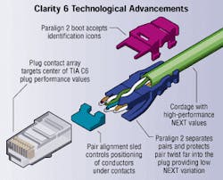
The exacting specifications of high-performing patch cords have changed the way manufacturers produce their cords. Ortronics, for example, uses a plug-and-termination process it calls Paralign 2 in its Category 6 patch cords. The company's Category 6 product line carries the brand name Clarity. According to Ortronics, the termination process "maintains pair integrity from the point of exit from the cable jacket to the contact termination point."
Ortronics' Lafontaine explains, "When pairs are in the cable, they are in their most stable state. The Clarity cords continue to control the pair-to-pair relationship after exiting the jacket. The geometrical positioning allows pairs to maintain their natural relationships."
There is more to a Clarity cord than simply a length of cable and a plug. The cable fits into a piece called Paralign 2, which separates pairs and protects pair-twist far into the plug. A pair-alignment sled controls positioning of conductors under contacts. And the plug contact array targets the center of the TIA's Category 6 plug-performance values. The Paralign 2 boot accepts identification icons.
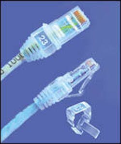
Similarly, HellermannTyton's Giga Band Category 6 cord uses patented manifolds inside the plug that maintain pair-twists and reduce NEXT of the plug. HellermannTyton's Category 6 cords also feature an identification window as a separate snap-on piece. "The clear window is magnified," explains Bernstein. "The user can print a label to go into the window. With the new 606A standard coming out, there is heavier emphasis on labeling all around."
And like other cord makers, HellermannTyton kicked engineering into a higher gear to produce Category 6 products. "Small steps can make a big difference in performance," notes Bernstein. "Manufacturers either crimp or overmold their plugs onto the cable. We overmold our Category 6 plugs onto the cable. We feel overmolding has a variety of benefits, including slightly better system performance." Most manufacturers, he points out, are not recommending field terminations of Category 6 cords.
Cord bend radius
Patch cords have been a topic of study within the TIA for reasons other than de-embedded plug values. After years in various stages of study, a proposal to specify a minimum patch-cord bend radius has passed. The wording within Addendum 1 to the TIA/EIA-568B.1 standard specifies the minimum bend radius for unshielded twisted-pair (UTP) patch cords at 1/4-inch. The addendum also specifies the minimum bend radius for screened twisted-pair patch cords at 2 inches.
Dennis Mazaris, president of PerfectSite (www.perfectpatch.com), championed the bend-radius specification effort. "Dennis essentially took it on his own," says Herb Congdon, director of systems marketing at Tyco/AMP Netconnect, vice chair of the TR-42.1 committee and chair of the TR-42.8 committee. "He did a number of reports. Questions surrounded whether or not a bend that tight would create a problem. There have been skeptics."
"When you bend the cord," explains Ortronics' Lafontaine, "the internal elements bend as well. You may or may not go outside the natural lay of the conductors."
The concern over what might happen with such tight bends was the basis for much of the resistance and skepticism of the 1/4-inch proposal. But Mazaris maintains that two facts should prevail:
1) The test results he produced at several TIA meetings back up the idea that a 1/4-inch bend radius for UTP cords does not harm channel performance.
2) His proposal made it through the rigors of the TIA standards-creation process and ultimately was ratified.
Mazaris has always maintained that his proposal is about patch-cord slack management in telecommunications rooms. He says that the use of patch-cord managers alone is most often insufficient. "If you tried to achieve patch-cord management simply through managers, you would end up weaving the cord in and out of the managers to get rid of the slack," he says. "That approach is not really effective because most users plug one end of the cord into one outlet, and the other end into another outlet, and that's it."
Mazaris designed and sells a product called PerfectPatch, which includes two plastic clips, takes up as much as 60% of a patch cord's slack, and requires the bending of cords to just about 1/4-inch. "I could have made the product with a larger base, which did not require cords to be bent as much as 1/4-inch," he says. "But a product with a base that large would not achieve the same level of slack management."
The 1/4-inch radius specification applies to UTP patch cords only-not to UTP horizontal cable, and not to any optical fiber cable.
Patrick McLaughlin is chief editor of Cabling Installation & Maintenance.
Did you know?
Under specifications in the recently passed TIA/EIA-568B standard, the allowable lengths of patch cords in the work area and in the telecommunications room have changed. Previously, users were allowed 3-meter cord lengths at the work area and 6 meters in the telecommunications room. Under the new specifications, users are allowed 5-meter work-area cords and 5 meters of cord length in the telecom room.


