The right tools for accurate fiber-optic testing
by Jim Hayes
Despite its reputation as a highly accurate measurement device, the OTDR is only one part of a comprehensive strategy for testing fiber links in the premises.
It's common for the customer of a fiber-optic cable installation to require documentation of test results before accepting the job and paying for the work. This obviously leads to certain but often conflicting requirements for the contractor. Testing takes time, so completing all of them in the minimum time means more profit.
Testing, however, needs to be done carefully toensure the measurements are accurate—that is, the measurement made gives a value close to the "real" value. And that can take time. Accurate testing will ensure that no good cables are rejected and no bad ones missed, so the contractor will not have to repair what are really good cables and get callbacks on bad ones.
Lots of time and cost can be saved if you as contractor and your installers know the proper measurements that need to be made, understand how to make those measurements correctly, have the proper tools, keep them in good condition, have them calibrated regularly, and know how to use them efficiently. You also need to convey to the customer that what is being done is in line with industry convention and standards.
Industry committees spend massive amounts of timeand energy developing standards that ensure accurate testing. But those standards are generally written for manufacturers, not users. This tutorial will give you insight into what tests are required, what problems are inherent in testing multimode fiber, how measurement techniques differ, and how to interpret and document the results.
How to test premises cables
In premises cabling systems designed for use with LAN backbones, fiber-to-the-desk, closed-circuit television, industrial control signals, etc., there are three tests that may be done: connection verification, insertion loss, and optical time-domain reflection. All cables should betested for continuity with a visual fault locator or fiber tracer, and the connections verified.
In my experience, many fiber-optic cabling problems are caused by poor documentation or confirmation of connections. Since each link consists of two fibers, onefiber must connect a transmitter to a receiver and theother the complementary pair. Documentation andmarkings should allow these connections to bemade simply. This is easily confirmed with avisual light source coupled into the fiber.
End-to-end measurements
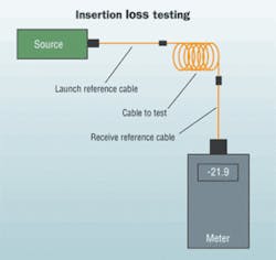
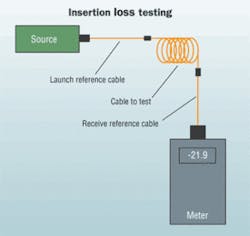
The measurement needed for confirming the quality of the installation is the optical loss or insertion loss of each of thefibers in the cable. Loss measurements are made end-to-end on the permanently installed cable plant—the equivalent of the unshielded twisted-pair (UTP) permanent link. Industry standards call for making that measurement with a test source and optical power meter, sometimes called an optical losstest set (OLTS) and reference test cables.

Proposals have been made to also allow for testing of installed cable with just an optical time-domain reflec-tometer (OTDR), but no accepted standard requires this. TIA-568 (both the B version and the soon-to-be-published C version) follows the industry convention, requiring insertion loss testing (called Tier 1 testing in TIA-568) and permitsOTDR testing also (Tier 2) to provide additional information, but does not allow OTDR-only testing in lieu of insertion-loss testing.
OTDR testing of premises cable plants instead of insertion-loss testing causes much confusion among contractors and customers. Hardly a week goes by that I do not get a callregarding this issue. Misinterpretations of these requirements have led to some unhappy instances, including misreadingOTDRs causing the removal and discarding of $100,000worth of good cable and the retesting of 1,100 cables of12 fibers each, as well as several instances of customers return-ing OTDRs to the distributors who sold them the units.
There are five industry-standard ways to test premisesfiber-optic cable (three for insertion loss and two for OTDRs), depending on how you use reference test cables for your setup. Insertion-loss testing can use one, two, or three referencecables to set the "zero dB loss" reference for testing, and each way gives a different loss. Generally, standards prefer the one-reference-cable loss method, but test equipment must use the same fiber-optic connector types as the cables under test. If the cable has different connectors than the test equipment (e.g., LCs on the cable and SCs on the tester), it may be necessary to use a two- or three-cable reference, which will give a lower loss since connector loss is included in the reference and will be subtracted from the total loss measurement.
Any of the three reference methods are acceptable, as long as the method is documented. Be careful, however, since most network link losses assume a one cable reference, which can affect the acceptance of the cable.
OTDRs require a launch cable for the instrument to settle down after reflections from the high-powered test pulse overloads the instrument. OTDRs have traditionally been used with long-distance networks where only a launch cable is used, but this method does not measure the loss of the connector on the far end. Adding a cable at the far end allows measuring the loss of the entire cable, but negates the big advantage of the OTDR—that it makes measurements from only one end of the cable.
All these test methods have seriousissues with accurately testing multimode cable. In the 25 or so years I have been involved with fiber-optic standards, making accurate loss measurements on multimode fiber has been a constant and confusing subject of discussion within the standards committees. We tried to understand how light travels in multimode cable plants and how components, such as connectors, affect the way that light travels. Then we tried to understand how the losses of fiber, connectors, and splices were affected by the methods used for testing.
What follows is how this works, how it affects your measurements, and how you can try to control test conditions toenhance your test accuracy.
How light travels in multimode fiber
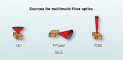
The most important component affecting loss in a multimode cable plant is the source-coupling light into the fiber. Light sources may be light-emitting diodes (LEDs) or lasers. Lasers may be VCSELs (vertical cavity surface-emitting lasers) or Fabry-Perot lasers (telecom style). Each of these emits light in a different pattern, with LEDs having the broadest beam, Fabry-Perot lasers a very narrow beam, and VCSELs in between. The light coupledfrom the source is transmitted in a multi-mode fiber in many rays or "modes;"hence, the name multimode.
A laser couples light only into modes that travel near the center of the fiber while a LED couples light into practically all the modes. Look closely and you can see the modes near the center of the fiber core (lower-order modes) travel shorter paths than those near the edges of the core (higher-order modes.) The shorter path of the lower-order modes means that they travel through less glass and suffer less loss than the ones traveling in the outside of the core. That means a laser suffers less attenuation (loss per unit length, in dB/km) in the same multimode fiber than a LED.
Furthermore, as light travels down the fiber, the attenuation changes. The light in the outside modes is attenuated, leaving mostly light in the modes near the center. At a kilometer from a LED source, the light in the outer modes is mostly attenuated and the light carried in the fiber looks more like the light launched from a laser. This means the attenuation at that point is less than at the beginning because it's only in lower-order modes.
So, what is the loss of the fiber? The manufacturer's spec for fiber is around 3 dB/km at 850 nm and 1 dB/km at 1300 nm, for a test using a calibrated source that is much closer to the launch of a laser source than a LED. The difference in the attenuation coefficient of a fiber tested with a laser or LED can be 1 to 2 dB/km. With a LED source, the first hundred meters of fiber (representative of a premises network) may have an attenuation of over 4 dB/km.
The same factors hold for connector and spice loss. Most of the loss in connectors is due to misalignment of the two fibers, and the higher-order modes are much more likely to be lost at a connector than are lower-order modes. A connector coupled to a LED source with a short cable could have a loss of 0.5 dB, while if it were coupled to a laser source, or were 1 km away, could have a loss of 0.3 dB.
By now, I suspect your head is swimming. If you still have your wits about you, you may want to know how any standards body can solve this issue. The answer is how everything is solved: Compromise. Create a standard launch condition that is more than a laser but less than a LED, which today isappropriate, since it's more like the VCSELs used in today's gigabit and faster multimode links.
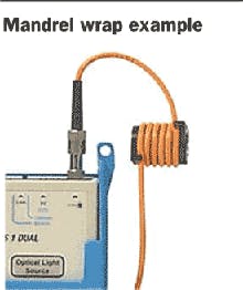
Manufacturers use special lensed sources in their labs that can precisely control the launch conditions. To approximate this launch for field testing, use a LED source and a mode modifier—usually a few turns of the reference launch cable around acylindrical mandrel that filters out thehigher-order modes. Choose the mandrel size according to the fiber and cable typebeing used. These devices are availablefrom many test equipment manufacturers.
This standard source method will produce more consistent test results and provide better reproducibility if you ever have to retest. And the losses measured are going to be lower, so you are less likely to fail good cables.
Even so, the uncertainty of the measurement is likely to be several tenths of a decibel. The uncertainty comes from the coupling of your reference cables to the fiber under test, which includes the quality of the terminations on the reference cables—how clean they are, and how many times they have been used—since they degrade with use.
Some people think everybody usesOTDRs for fiber-optic testing, but that's only for outside plant (OSP) applications. Most OSP installations involve splicing singlemode fiber to get longer runs, and the OTDR allows verifying the quality of the splice. But when that link is finished, it must still betested for insertion loss with a light source, power meter, and reference cables—just like premises cables.
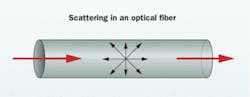
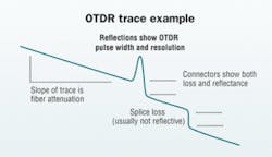
Insertion loss and OTDR testing use different methods. Insertion loss tests just the fiber that will be used, with a source on one end and a detector on the other. So, tested insertion loss should be close to what the communications linkactually will see. OTDRs, however, make an indirectmeasurement, based on fiber scattering—the major source of loss of a fiber. It sends a very powerful pulse down thefiber, and some of the scattering comes back toward theinstrument where it is measured and stored. As the test pulsemoves down the fiber, it takes a "snapshot" of the fiberilluminated by the test pulse from which informationabout the fiber may be implied.
OTDR limitations
Everything the OTDR learns about the fiber depends on the amount of light scattered back toward it and how it is set up for the test. This "backscatter" is a function of the materials in the fiber and the diameter of the core. Joints between two dissimilar fibers that have different backscatter coefficients will not allow one-way measurements—one way the loss is too high, the other way too low (perhaps a "gainer" where the change in backscatter is more than the loss of the connection).
The second problem with OTDRs on multimode fiber is the laser source. As mentioned, lasers couple light narrowly into multimode fiber and will measure lower attenuation and connector- or splice-loss than recommended on the outward-bound test pulse. But scattered light probably overfills the fiber, even morethan a LED on the return. To date, we are unaware of anyone who has modeled this and can provide guidance on the expectedtest results from an OTDR.
In addition, there are problems in premises applications with OTDR distance resolution. Light travels about 1 meter in 5 nanoseconds (ns). The width of the test pulse is usually 10 to 30 ns and the minimum resolution of the OTDR is about three times that, or 2 to 6 meters. Highly reflective events, like multimode connectors in premises cabling, cause instrument overload and lengthen the instrument's minimum resolution. Only a few specialized OTDRs have the resolution needed for premises cabling.
Before you use an OTDR to make a measurement, you'll have to set all of the following parameters correctly: Range, wavelength, pulse width, number of averages, index of refraction of the fiber, and the measurement method (usually two types for each measurement.)
OTDR manufacturers should teach you how to properly set up the unit and interpret the rather complicated display. But since few customers are willing to invest the day or two necessary to learn how to use the instrument properly, manufacturers create an "autotest" function, like a Category 6 certifier that tests the fiber and gives you a pass/fail result. Everydebacle I have seen in OTDR testing has resulted frominadequately trained personnel using autotest.
Unfortunately, because of their indirect measurement technique, OTDRs do not easily correlate with insertion loss tests, and that's why they are not approved by industry standards to be used alone. Some users claim to have been able to control modal power in multimode fiber and get correlation between OTDRs and insertion-loss tests. But results are hard to duplicate. The Fiber Optic Association did a comprehensive comparison test using special mode conditioners and we were unable to get correlation. In fact, some of our tests gave divergent results between two different OTDRs.
If you consider the OTDR test to be a "qualitative"rather than "quantitative" test, and know how to interpretthe trace properly, you can determine if connectors andsplices are properly installed and if any damage has been doneto the cable during installation. But if you or the user do not have the experience and knowledge to do a proper analysis, an OTDR alone can cause problems.
Getting it accurate
To test efficiently and accurately, as contractor, you and the customer should agree on what documentation and testingare required before the project is started. Documentation should include the layout of the cabling, types and numbers of fiber in each cable, connection diagrams, andinsertion-loss test results. That agreement should be part of the bid and the contract. If the customer wants OTDR data, help them to understand that OTDR testing can be time-consuming and expensive.
Before beginning the installation, calculate a loss budget for each link based on the length of the link and the number of connections. This confirms the equipment will operate over that link. Then, the expected loss will be known to allow a pass/fail decision by the person doing the testing.
Make sure you have the proper test equipment, and that installers are familiar with its use.
When terminating cables, test eachcable with a source and power meter using high-quality reference cables. The accuracy of the measurements depends on having properly operating test equipment, high-quality reference cables with a mandrel wrap, cleaning all connections before every measurement, and using a consistent measurement technique.
Test the reference cables with the same test equipment each day, and clean carefully before each measurement. All installers should be familiar with using the mandrel wrap on the launch cables.
Because the light source and power meter insertion loss test requires an instrument at each end of the cable, two installers working together will speed up the process. You can use a visual tracer to identify the next fiber to test, making communication easier and cheaper than using cell phones.
Data should be recorded in a spreadsheet alongside the loss-budget calculation used for pass/fail criteria so that you and the customer can verify the installation.
Troubleshoot high-loss links that fail testing by testing "single ended" with only a launch cable. Bad connections will show up as high loss when connected to the launch cable but not when connected directly to a power meter. So, reversing the cable test direction will usually find bad connectors.
JIM HAYES is president of The Fiber Optic Association, Inc. (www.thefoa.org), the professional society of fiber optics. Originally educated as a physicist/astronomer, he co-founded fiber-optic test equipment company Fotec in 1981, which was sold to Fluke Networks in 2001. Jim has been training fiber-optic technicians for more than 25 years, and is the author of three fiber-optic textbooks and numerous technical articles. Additional information on installing and testing fiber-optic networks is available on the FOA "Tech Topics" website: www.thefoa.org/tech/index.html

