Extending fiber-optic cabling to the work area and desk
Extending fiber-optic cabling to the work area and desk
Fiber-optic cabling is beginning to make sense economically for many companies` premises networks.
Bob Jensen
3M Telecom Systems Div.
Deployment of fiber-optic technology in premises applications is not new. What is new is that optical fiber now has begun to serve all premises applications that require high bandwidth and fast data transmission, rather than being relegated to the backbone or used in horizontal cabling only in limited circumstances.
Fiber installation beyond the backbone is already taking place at leading-edge technology companies and universities. Companies that have waited on general acceptance of fiber-to-the-desk have also begun to consider fiber as a cable alternative. This growing acceptance is due to the advent of new standardized optical-fiber cabling designs and recent interconnect options that position fiber as the cost-effective medium of choice for premises cabling, up to gigabit data rates.
Fiber becomes standard
The principal advantage of deploying optical-fiber cabling instead of older copper cabling is that it carries telecommunications transmission farther at higher data rates. Fiber`s higher bandwidth and lower attenuation compared to copper make this possible. And data streams over fiber-optic cabling are immune to such copper-cabling problems as near-end crosstalk, far-end crosstalk, equal-level far-end crosstalk, power-sum equal-level far-end crosstalk, and typical copper-cabling return loss.
Other differences between copper and fiber that affect cabling installation include cable pull strength, bend radius, cable weight, and termination practices. For example, the pulling tensions for horizontal fiber-optic cables are four times the recommended pulling tension for 4-pair copper cable.
Prior to the general acceptance of cabling standards, cabling was randomly installed as needed by the end user. Once cabling standards became generally accepted, the cabling began to be installed in an organized structured cabling system. In the days of ansi/eia/tia-568 standards (prior to iso/iec-11801 or tia/eia-568a), there was only one way to design the network. The basic design comprised a backbone cable interconnecting the main crossconnect to intermediate crossconnects in other buildings or to telecommunications closets (TCs), and a horizontal cable that extended to the work area outlet from the TC.
Over the years, innovations in cabling design architectures have been approved within standards groups. These architectures include open-office architectures that incorporate consolidation points and multiuser telecommunications outlet assemblies (MUTOAs) that are addressed in tia/eia telecommunications systems bulletin TSB-75, "Additional Horizontal Cabling Practices for Open Offices," and centralized cabling (collapsed backbone) addressed in tia/eia tsb-72, "Centralized Optical Fiber Cabling Guidelines."
When designing copper or fiber-optic cabling systems, there is little difference in the steps and thought processes involved. However, copper systems are designed for a bandwidth up to 100 megahertz at a maximum distance of 100 meters (328 feet), while fiber-optic cabling systems far exceed these limitations.
These greater fiber-cabling distances can be used to the designer`s advantage in planning the location--or elimination--of a TC. Fiber distances vary depending upon the application being used but easily fit into a structured cabling design.
Three major cabling architectures are typically recognized: distributed cabling, open-office cabling, and centralized cabling. Among these three, centralized cabling takes greatest advantage of the extended distance capability of optical-fiber cabling.
Centralized cabling
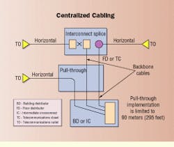
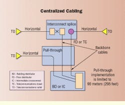
Centralized cabling was introduced in October 1995 through standards adoption of TSB-72. The collapsed backbone system can extend from the main crossconnect or intermediate crossconnect, which is usually at a central point in a building within the system, to the telecommunications outlets. This architecture may include campus and building backbone cable (which may be combined as indoor/outdoor cable) and horizontal cable that extend to the terminations at the telecommunications outlets.
The basis for a centralized cabling system lies with the bandwidth capability of the fiber cable being designed into the system. For instance, when using a 62.5/125-micron optical-fiber cable having a 200-MHz-km bandwidth at the lower window of 850 nanometers for centralized cabling, a channel distance up to 275 meters (900 ft) is recommended to accommodate the IEEE 802.3z Gigabit Ethernet standard. When using other fiber cable, the manufacturer should be consulted on the achievable distance.
The designer must remember that this operating distance is for the entire channel, which includes the equipment and patch cords--from the centralized equipment location to workstation terminal equipment locations. In addition to these extended distances for fiber-optic cabling, allowances are made in TSB-75 for both copper and fiber cabling to be centralized when the work area to be serviced is within 100 meters (328 ft) of the centralized equipment for the channel.
Placing an interconnect within the TC is generally not recommended when implementing centralized cabling in combination with open-office cabling. Interconnections will only increase installation and maintenance costs, as the administration will typically be handled in the open-office area. In these situations, a splice is recommended where necessary, such as when connecting large-count backbone cables to horizontal cables. The authors of the Telecommunications Industry Association cabling standards did not envision the incorporation of centralized cabling with open-office cabling due to these administrative headaches.
Cable installation is yet another important consideration in the design. For instance, is it easier to place 96 2-fiber horizontal cables in a sleeve through the floor rather than placing two 96-fiber cables? The designer must also consider the ease of properly firestopping these sleeves.
In addition to installation and administration, the cost of the cabling system is a primary consideration. The applied cost of a centralized network is generally significantly less than that of a distributed network over time. Using a centralized architecture in a building reduces the need for TCs to be built on each floor. Instead, a cable pathway is needed through a TC, thereby diminishing the closet size significantly. Cost savings are realized from the elimination of electrical, heating, ventilation, and air conditioning, not to mention the cost of floor space, maintenance, troubleshooting, and network management.
Distributed horizontal cabling
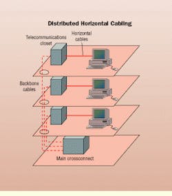
Distributed cabling stems from eia/tia-568, "Commercial Building Telecommunication Cabling Standard," and eia/tia-569 standards. The eia/tia-569 standard was later revised to accommodate open-office cabling and centralized cabling. In a distributed system, each of the horizontal cables must support transmission to 90 meters (295 ft) for a basic link and 100 meters for a channel. tia/eia-568a recommends that a minimum of two outlet/connectors be installed at each outlet location. But with the increase in telecommunications needs, a minimum of three outlet/connectors is recommended at each outlet. One unshielded twisted-pair (UTP) outlet is needed for voice (via Category 3 or 5 cable) and two outlets for data. Ideally, the configuration would contain one UTP for voice (Category 3 or 5); one UTP for low-speed data such as modems or fax; and two 2-fiber connectors for mid- to high-speed data. The installation of these media in a distributed cabling architecture provides a 2-connector basic link for each cable.
Open-office cabling
Another cabling architecture used with fiber is open-office cabling (TSB-75), which provides for the installation and maintenance of cabling through the ease of zone cabling. Zone cabling uses two approaches to cabling: MUTOAs and consolidation points.
A MUTOA provides for a location with multiple outlets that facilitate the extension of work-area cords from the building distribution system to furniture systems. A MUTOA allows equipment cords to feed through furniture systems and connects directly to the terminal equipment such as the telephone, fax, or personal computer.
The implementation of a MUTOA is similar to that of a distributed horizontal cabling implementation using fiber-optic cabling. However, when implementing a copper-based system, there is a slight shortening of the channel due to the additional attenuation imposed by stranded copper equipment cables.
A consolidation point could also be implemented in the cabling architecture of the building, since it allows for an additional administration point similar to that of a MUTOA. A consolidation point differs from a MUTOA in that it provides a point of interconnection between the horizontal crossconnect and the telecommunication outlets.
Fiber selection
When installing a fiber-optic network, fiber size selection is entirely a matter of choice. Both 62.5/125- and 50/125-micron fiber-optic cable are commonly used. Some factors that should influence fiber selection are any future plans to migrate to new technologies that will require a change in media or if the fiber size currently used in the network will provide sufficient bandwidth headroom for future needs.
Two primary factors must be considered in fiber selection and system design: maximum system length and maximum channel attenuation. The maximum supported system length is based on bandwidth, transmitter and receiver specifications, propagation delay, jitter, and numerous other factors. The maximum channel attenuation is established by the minimum transmitter output, maximum receiver sensitivity and any power penalties established. The number of connections and splices, cable length, wavelength of operation, and loss values of components affect channel attenuation. In testing, attenuation readings with a light-emitting diode (LED) source will be higher than those of a laser used with 1000Base-SX, 156- and 620-megabit-per-second Asynchronous Transfer Mode, and 266-, 531-, and 1062-Mbit/sec Fibre Channel.
The two multimode fiber sizes can be easily mixed in the cable plant. But when mixing 62.5/125- and 50/125-micron cable, the average difference in power is expected to be within 3.5 to 4.7 decibels. In calculating the power budget, a power penalty only needs to be taken once, despite the number of connections.
Both 62.5/125- and 50/125-micron fiber-optic cabling meets or exceeds all the performance requirements of the existing and known forthcoming national and international cabling standards and will support the most stringent laser- and LED-based applications. Among these standards is the recently approved IEEE 802.3z for Gigabit Ethernet, whereby the worst-case operating distance is up to 275 meters for 62.5/125-micron fiber with a 200-MHz-km bandwidth at 850 nm and up to 550 meters (1800 ft) for 50/125-micron fiber with a 500-MHz-km bandwidth at 850 nm.
Fiber-optic interconnection
Once fiber selection is determined, considerations for channel design are tied to the interconnect style selected for the installation. The basic requirements for any fiber-optic connector are to align two fiber-optic cores (about the size of a human hair) and prevent them from being disconnected. Recent advances in fiber-optic connector designs are contributing to the acceptance of fiber-optic networks.
The industry is currently designing products for two categories of interconnects. First are traditional designs such as the ST-type or SC connector, and the second category is a new generation known as small-form-factor (SFF) connectors that are generally half the size of the traditional fiber-optic connectors.
Greater port density
Development of SFF connectors has opened the door for greater port density for fiber optics, making it possible to connect 24 fibers on a switch or hub where only 12 previously fit. This new density level matches that of the copper RJ-45-type port, making it easier for fiber to coexist with copper in the network and at the wall outlet. In addition, some SFF connectors incorporate an RJ-45-style latching mechanism for familiarity, offer decreased installation time, and support duplex fiber preparation, allowing two fibers to be terminated at once.
Interconnect cost is an important consideration in network design because of the number of connectors needed in the office area and TC. For example, with VF-45 ferruleless SFF connector technology, a sevenfold savings in unit cost over the price of standard SC connectors can be realized.
Whether an SFF design is selected or a traditional SC or ST connector is used, channel attenuation is affected by the number of connections and splices, cable length, wavelength of operation, and loss values of the components. There are several common equations used to calculate channel attenuation, such as the Monte Carlo simulation model or the Fiber Distributed Data Interface model.
This article is reprinted from the April 1999 issue of Lightwave, another PennWell publication.
Centralized cabling architecture reduces the need for sizable telecommunications closets on each floor.
Considered a traditional cabling architecture, distributed hori-zontal cabling must support transmission to 90 meters (295 ft) for a basic link and 100 meters (328 ft) for a channel.
Bob Jensen, registered communications distribution designer (RCDD), is the technical services team leader for the Volition Cabling System at 3M Telecom Systems Div. (Austin, TX). He chairs the TIA subcommittees TR-42.2, Residential Cabling, and TR-42.3, Pathway Fill Task Group.


