Testing capabilities provide benefits in the field and in the lab.
Mark Johnston
Microtest
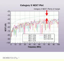
Installers familiar with testing legacy Category 5 links have grown to expect plenty of near-end crosstalk (NEXT) margin between the pass/fail line and a typically performing link. The quality of cable and connecting hardware, as well as installation skill, has increased to a point where it is unusual to see a Category 5 NEXT failure.
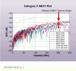
With Category 5E and Category 6, however, conditions have changed. These standards necessitate new, complex measurements such as return loss, power-sum NEXT, equal-level far-end crosstalk, and power-sum equal-level far-end crosstalk. Rather than stopping at 100 megahertz, Category 6 links are tested to 250 MHz. And most importantly, the typical margin between a link and its pass/fail line is much tighter than was the case with Category 5. With tighter margins, higher frequencies, and new measurements, there will be more failures, the cause of which can be subtle.
Recent contributions to the Telecommunications Industry Association (TIA--Arlington, VA) show that patch-cord quality can have a significant effect--up to 5 decibels--on overall link performance for NEXT and return loss. Clearly, continuity testing is no longer sufficient for patch-cord qualification. How can manufacturers ensure their cords meet new TIA performance guidelines?
Current diagnostic alternatives
When diagnosing field failures, component substitution--often called "swap and pray"--is a common approach. While inefficient, this technique sometimes works for a bad termination or defective component. But if the problem is due to poor system design or a bad batch of components or cable, you can swap all day long with no improvement.
A key to solving these issues lies with understanding how performance of a component or link varies over a distance. This understanding allows you to see the relative magnitude of NEXT or return loss in a patch cord, at a connector, or in the horizontal cable. First-generation approaches to this diagnostic technique were helpful for gross Category 5 problems, but suffered several disadvantages. For example, a time-domain reflectometry (TDR) measurement shows you impedance versus distance. However, impedance is related to, but different from, return loss. More importantly, while a sense of the relative magnitude is given, there is no way to distinguish subtle differences that can cause a failure on Category 5E and Category 6 links.
Similar challenges limit the usefulness of first-generation crosstalk-versus-distance measurements. Crosstalk-versus- distance is not NEXT-versus-distance; there is no indication of pass/fail values, and there is no way to see if you`re dealing with a large-point source of crosstalk (a connection) or a long series of distributed NEXT sources (the horizontal cable) as the cause of a link failure.
A newly developed technique eliminates the shortcomings of previous approaches. Time-domain NEXT (tdnext) and time-domain return loss (TDRL) with S-Band technology provide a method to quickly, easily, and definitively pinpoint the exact cause of a failed link.
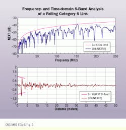
S-Bands (standard connector bands) are pass/fail limits for connections in the time domain. If a link fails NEXT, for example, a tdnext test will show whether the failure is due to the connection or the cable. Because the connection is a point source of NEXT or return loss, the performance of a connection in the time domain at Category 5, Category 5E, Category 6, and Category 7 levels can be computed for any distance away from the field tester. These points form a set of curves that become pass/fail lines. If the link fails, S-Band analysis will tell you instantly whether it`s due to the connection or the cable. The unique advantage is that S-Band analysis provides a nondestructive way to determine whether installed components meet desired performance. S-Band analysis is patent-pending and is available in the OMNI-Scanner, a handheld testing tool from Microtest.
Production-line testing
With the development of appropriate fixturing, it is now possible to qualify patch cords in a production environment using a new generation of field testers with Level III accuracy. This testing requires the construction of laboratory-qualified interfaces that are in compliance with the latest TIA PN-4349 draft, which describes a production patch-cord test methodology. Test results show that the method can be used to verify patch cords to Category 6 performance levels.
Several recent articles have pointed to the patch cord as the weak link in a channel. The tia/eia (Electronic Industries Alliance--Arlington, VA) held up publication of the Category 5E standard until it could resolve the problem of channel return-loss failures caused by poorly performing patch cords.
nordx/cdt (Pointe-Claire, QC, Canada), a manufacturer of end-to-end structured-cabling systems, recently completed the development phase of its IBDN 2400 and 4800LX systems. With the development complete, the company needed an easy and nondestructive method to test the new patch cords up to 300 MHz in a factory environment. According to Paul Kish, senior product manager of nordx/cdt, "We thoroughly evaluated one of the OMNIScanner units on the market to ensure consistent and accurate measurements compared to a network analyzer. We worked closely with Microtest to identify and correct measurement discrepancies that were due to the measurement setup. We were satisfied that the unit performed to expectations."
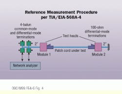
The tester`s interface was adapted to test the nordx/cdt PS5 (Category 5E) and PS6 (Category 6) patch-cord assemblies. The test setup was based on the production patch-cord test procedure that is currently being balloted within the TIA as proposed Addendum 4 to the tia/eia-568a cabling standard. The OMNIScanner replaces the network analyzer and the four baluns in the TIA`s test setup. Also, module 1 is mounted on a printed-circuit-board interface that plugs into the main test unit--commonly referred to as the test boot. The far end of the patch cord is terminated with precision 100-ohm resistors through a modular jack of the same design as module 1. For test purposes, module 1 and module 2 are nordx/cdt PS6 jacks. The test requirements for patch cords were programmed into the unit based on the proposed Category 6 specifications for connectors and cable.
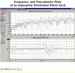
The time-domain analysis feature is resident in the unit, or users can download it to a personal computer. The feature allows examination of NEXT coupling or return loss as a function of time or distance from the transmitter. For example, a failure that occurs between 13 and 15 nanoseconds from the transmitter is located 2.6 to 3 meters from the tester when you use a velocity of propagation of 5 nsecs/meter for the cable.
Connector-design verification in the lab
The Category 6 draft standard is progressing rapidly, and many products claiming compliance with Category 6 are now available. For many Category 6 links, however, connecting hardware is the weak link. Many reports of marginal link performance have been reported from the field. But how can you find the culprit in such situations? When structured-cabling-system manufacturer Siemon Co. (Watertown, CT) developed connecting hardware designed to comply with Category 6 and Category 7 requirements, the company needed to quickly and accurately determine the impact of design changes on connector and link performance. What impact did a design change have on patch-cord, connection, and cable performance in an installed link? Were connector designs interoperable with other manufacturers` products?
While a skilled engineer can conduct this analysis using a network analyzer, this approach is time-consuming and expensive, requires an expert to interpret results, is not portable, and does not clearly differentiate effects caused by point sources from effects caused by distributed sources of NEXT or return loss. The Siemon Co. found that because OMNIScanner results were equivalent to those of a network analyzer, S-Band analysis provided fast, reliable, and definitive verification of component performance. "Many end users are having difficulty sorting through the hype when comparing manufacturers` Category 6 performance claims," says Valerie Rybinski, senior engineer at the Siemon Co. "To identify the highest-performing cabling system, we strongly recommend objective, side-by-side field testing of Category 6 products using the OMNIScanner and S-Band analysis."
Field-troubleshooting systems
Earlier this year, BMW Communications (Sanford, FL) installed a proposed Category 6 structured-cabling system made from components supplied by two well-known manufacturers in the cabling industry. The crew from BMW Communications installed 480 nodes, and the manufacturers guaranteed that the entire system would meet the current proposed Category 6 requirements.
However, when it came time to certify the installation, field-testing provided a shocking result: 480 failures, all due to NEXT. Everything appeared to be fine, yet the links failed NEXT requirements every time.
The customer understandably refused to pay. Jim Maxin, registered communications distribution designer (RCDD) and vice president of operations for BMW Communications, recalls, "Weeks went by, with increasing frustration from all parties involved. We knew something wasn`t right. But we had no way to prove what it was." At that time, Microtest made available a beta version of S-Band diagnostic technology to see if it could help solve the problem. "That new software pinpointed the problem instantly," Maxim adds. "The cable was fine, but the connection was nowhere close to Category 6 requirements."
Once shown the technical data, the connector manufacturer took responsibility for the problem. The installation company replaced the noncompliant parts and the installation passed easily.
A new breakthrough in diagnostic technology that instantly and accurately differentiates the cause of marginal link failures in Category 5E and Category 6 systems, S-Band technology is being used in production facilities and laboratory environments to assist experts in developing and testing advanced components and patch cords.
A typical Category 5 diagnostic readout shows plenty of margin between the top, pass/fail line for near-end crosstalk (NEXT), and the lines that indicate the NEXT performance for each of the pairs in a link.
Many links of cable and connectors from manufacturers claiming to meet the proposed Category 6 standard narrowly pass the draft Category 6 NEXT requirements.
The S-Bands in the time-domain plot of this marginally failing Category 6 link indicate that the connection, located 2 meters from the test set, fails to meet NEXT requirements and therefore is the cause of this link failure.
The reference measurement procedure used by the TIA to test patch cords includes a network analyzer, four common-mode and differential-mode terminations using baluns, two modules, test heads, and 100-ohm differential-mode terminations.
The time-domain trace of this failing patch cord shows that the cause of the failure is the far-end connection, occurring between 13 and 15 nanoseconds, which corresponds to a distance of 2.6 to 3 meters.
Mark Johnston is director of technology development at Microtest (Phoenix).
