Maintaining fiber-optic cable at the demarc

Who does what at the junction of the public and private networks?
Jel K. Matthews
To the traveler, the border crossing is invisible: no armed guards, snarling guard dogs, passport checks, or luggage searches. To the signals crossing this border, it might as well not even exist; but to your network managers and technicians, it`s a critical crossing. The border is the demarcation point, or "demarc," between your fiber network and that of your service provider. On the outside, the service provider handles maintenance; on the inside, the responsibility is all yours.
Every installation involves tough choices. Users need service, nobody wants to wait, and cost is a constant issue. Faced with the competing demands for service, speed, and savings, you may be tempted to do the job "well enough for now," with the rationalization that it can be fixed later. If, as a network builder, you find yourself asking, "Why not?" The answer is simple: "Y2K."
The impending Y2K nightmare is a classic result of short-term thinking. Programmers came up with what they considered a safe, simple fix to a relatively small problem. They assumed that the fix would be replaced long before it, in turn, became an issue in its own right. In fact, the "fix" stayed in place and became a ticking time bomb that will likely cost billions of dollars before it is resolved.
In much the same way, we are now in the early days of fiber networking. It may seem that we are installing enormous amounts of capacity, but experience tells us that demand always grows faster than expected. Chances are excellent that over relatively few years,
- The bandwidth carried by existing fiber will increase more than expected.
- The amount of fiber cable in fiber troughs will grow faster than we assume.
- Much more equipment will be needed to support fiber infrastructure.
- The density of fiber on that equipment will increase.
- The complexity of fiber management will grow geometrically.
It is impossible to accurately anticipate future needs, but the responsible approach is to be conservative without skimping on details that could jeopardize network performance.
Making an entrance: the fiber demarc
There are two basic styles of fiber demarc: those at which inside and outside fibers are spliced together and those at which connectors join them. Which type you use depends on your internal architecture. If there is a main crossconnect (MC) relatively close to the demarc, you might prefer splicing incoming fiber at the entrance cabinet located there. Moves and changes can be accomplished at the MC, as can rerouting around failed fibers.
But if your architecture brings fiber to multiple locations (telecommunications closets, for example) directly from the demarc, the situation is very different. If a splice-based entrance cabinet were used, many moves, changes, or reroutings could be accomplished only by resplicing. In this case, a connector-based fiber entrance terminal would be far more preferable. The demarc`s crossconnect capability allows connection around internal or external failures, taking the place of the other architecture`s MC.
In both cases, the demarc should do more than merely terminate fiber; it should also protect it from damage and prevent excessive bending. In addition, it should provide protected storage for excess cable to simplify access and prevent damage. A wall-mounted unit saves space and provides flexibility in installation. If the location is not secure, a lockable demarc is preferable. Finally, it should provide features for clear routing and labeling to help manage growth and change.
Yet another kind of demarc is a terminal, or cabinet, that accommodates both splicing and connectorization.
The joy of splicing
By itself, splicing is relatively simple, reliable, and permanent. In reality, however, splicing tends to take place in difficult places and times, making the process much more complicated. First of all, it can take place in confined spaces with relatively little room to work. Second, it tends to take place where there are lots of other fibers, which can be disturbed in the process. Third, it can take place under time pressure, either in the course of a multifiber installation or to remedy a failure. There are several ways to simplify and speed splicing.
- Don`t use splices if you don`t have to. You can`t remedy today`s splice problems this way but you can prevent tomorrow`s. You may not be planning to grow, change, or repair, but Murphy`s Law suggests that you should.
- If you must splice, use a system that is splicing-friendly, providing easy access, splice trays, work space, fiber protection, lighting, and room to grow.
- Give yourself a break. Leave plenty of slack for convenient handling. Lay out your fibers so that repairing one won`t damage others.
-Allow enough time to do the job carefully. Rushing through a job increases the likelihood of damage now and sets you up for problems the next time you have to access the same splices.
Typically, splicing personnel (splicers) are skilled above and beyond the normal premises technicians. Splicers are often subcontracted out at considerable cost.
Making connections: frames and panels
Both during and after installation, most of your contact with the fiber will be at the frames and panels. Depending on the architecture you choose, these will be in some hierarchy of MC, intermediate crossconnects, and telecommunications closets (TCs). These are all critical places for your fiber.
- Connectorization allows greater flexibility than splicing, but just as a cut or scrape provides the opportunity for infection, a connector provides an opening for dust or dirt, which can disrupt data-signal flow.
-Complex routings, sharp turns, and untended slack provide ample opportunity for bend-radius violations, which can cause attenuation or even breaks in the fiber.
- Frequent handling affects both the fiber being handled and those around it.
- Poor fiber management can increase the amount of handling, resulting in slow installation or repair and increasing the likelihood of damage.
All of these problems can be alleviated with planning. The first step is to establish fiber-specific procedures. Once procedures are established, train your staff; many of the oversights that lead to problems will disappear.
Standardizing on equipment helps to standardize procedures. A single system throughout the facility will simplify inventory and shorten the learning process. Such a system should be modular and inclusive and should provide a range of options such as crossconnect or interconnect. It should cover all levels of facilities, from demarc to fiber frame to TC to the desktop. An integrated system also eliminates the risk of damage to fiber in transit from one piece of equipment to another.
A system should be completely free of sharp corners and provide physical management for cable from end-to-end. Convenience features like front and rear access speed up the installation process, reduce the chances of damage to fiber, and simplify connections.
Attention to detail: connectors
Properly selected and used, connectors can provide nearly perfect signal transmission, along with the convenience of fast, simple reconfiguration. To deliver high-speed, high-bandwidth service, however, they must provide a near-perfect interface. A small gap or misalignment can cause attenuation or total loss of the signal. On the other hand, if the connectors press the fiber end-surfaces together with too much force, the glass can be crushed.
Environmental variations are another consideration when selecting a connector and connector manufacturer. Connectors must be carefully designed and manufactured to avoid these problems, initially as well as over time and environmental variation.
- Fiber ends must be precisely shaped and polished to provide proper mating of the surfaces and avoid pits and scratches.
- Epoxies that hold the fiber in place must withstand extremes of temperature and humidity. If they do not, the fiber can "piston" or withdraw, leading to fiber damage or poor physical contact at the connector.
- In the event of failure, the ability to identify the manufacturer`s lot number can help identify other potential problems before they occur.
- To help eliminate any potential problems, components must be carefully tested using the best available equipment, which should be recalibrated frequently.
Installation and handling also affect the performance of connectors. Cleaning is critical and should be part of every installation or move. Careful handling of the installed connector as well as adjacent fibers and connectors can improve contact of the mating surfaces and prevent unnecessary fiber damage.
Going `round the bend
The cabling installer who looks at a fiber and asks, "What could go wrong?" is not a pessimist, but a realist. First of all, fiber is made of glass. Second, it can be subjected to some very trying conditions. Third, a fault can cause serious problems and be difficult to isolate and repair.
A leading cause of problems is the violation of fiber`s bend radius. Many of these problems occur long after installation but could probably have been foreseen and prevented. Here are three examples.
1) A fiber is run loosely around a sharp, sheet-metal bend. The natural stiffness of the fiber keeps the turn gradual and larger than the minimum bend radius. Later, the addition of other fibers adds bulk or weight, pressing the original fiber against the sharp edge and into a tight bend, causing attenuation or breakage. The only reliable preventive measure is the absolute avoidance of sharp edges throughout the system.
2) Connectorized fibers plugged straight into a fiber frame or panel at a 90o angle are pulled sideways across the panel to allow visibility and access. The bend just behind the connector may not violate minimum radius, but a hard pull on the fiber or careless handling can eventually force it into a tight right-angle bend. This design could cause signal attenuation or contribute to jumper failure. A simple solution to this problem is to make use of angled retainers, which reduce the sideways pull and improve both visibility and access.
3) Unmanaged slack in cables or jumpers allows them to form loops. Jostling of these loops can easily cause kinks that violate minimum bend radius. The solution is to take up all slack, even over short distances, with systems specifically designed to control bending.
Fiber trough systems
Continuous fiber running in fiber trough systems faces a whole different set of problems. While it is not "open" as it is at connection points, it can be more exposed, traveling through public areas of the facility. And while a fiber may go for years without being touched, it is also subject to accumulated pressure as newer cables are added to the run, increasing both weight and physical pressure that can lead to unanticipated problems.
For example, within a fiber trough system, fibers may run horizontally across an open "downspout" without any problem, until the weight of accumulated fiber starts pressing down over the opening. The bottom fibers will then be pressed against the angled edge between the horizontal and vertical runs and eventually bend. The best trough systems provide rounded corners and baffles that separate nonexiting fibers from those making the turn.
Systems should also provide the widest range of options: size, joints, and materials. Even color may be an issue, for both aesthetic and management reasons. Some less obvious issues may also be important. For example, a system that requires fewer supports may cost more to buy but less to install. Snap-together systems can simplify installation, but only if they do not sacrifice strength or require additional support that eats up the time and cost savings.
In-house network builders face the classic dilemma: Fight alligators or drain the swamp. The bad news is that even if you can keep up, the system itself will betray you as higher data rates make greater demands than existing systems can meet. The good news is that better equipment costs only a little more and can save a lot in installation and ongoing support costs. The same argument can be made for judicious overbuilding. The better news is that the payback begins almost immediately.
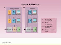
The network architecture influences whether you should splice or connectorize fiber at the demarc. In networks with a main crossconnect near the demarc, splicing is recommended (a). If the fiber goes directly from the demarc to telecommunications closets, it is best to use connectors at the entrance facility (b).
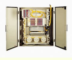
A secure fiber entrance terminal provides for both splicing and crossconnect capability.
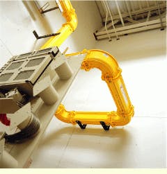
Fiber trough systems such as this one in a small telecommun-ications closet should be adaptable to different-size spaces.
Joel K. Matthews is product manager, fiber-optic products, at adc Telecommunications (Minneapolis, MN). For more information, visit www.adc.com.

