Using fiber-optic cable in security and surveillance
Tight-buffered cable’s ability to handle the outside plant makes it an option worthy of serious consideration.
Security and surveillance camera systems are now a vital application in the enterprise space, where optical-fiber connectivity has emerged as a primary media type. Separate LAN and security surveillance structured wiring installations are being deployed to facilitate reliable operation and ease of system management. Cabled multimode and singlemode optical fibers are being used to transmit high-quality analog and digital video signals over extended distances between video monitoring cameras and the network management center.
Optical fiber’s benefits
Optical-fiber cable offers the greatest bandwidth performance of any media type used in today’s security and surveillance camera systems. A recent trend in surveillance cameras is the migration to Internet Protocol (IP) to take advantage of low-cost Ethernet system electronics as well as digital transmission and the ability to interoperate with multiple security systems.
Multimode fiber is the dominant fiber type used for analog and digital Ethernet systems to 2 kilometers (km), while singlemode fiber is the choice for distance beyond 2 km in digital Ethernet systems. Optical fiber is a dielectric transmission medium that is not susceptible to electromagnetic interference (EMI) or radio frequency interference (RFI). No separation restrictions from EMI or RFI ingress sources, such as motors, fluorescent lights, or power cables, exist relative to indoor or outdoor placement.
Near-end and far-end crosstalk issues associated with copper unshielded twisted-pair (UTP) communications cables are not applicable to optical fiber. Copper UTP and coaxial cable are susceptible to ground loops, requiring surge protection in addition to environmental EMI. The dielectric nature renders optical fiber the most secure and reliable transmission method possible, as there are no EMI egress signals that can be tapped.
Physically tapping the fiber takes great skill to do so undetected. Once installed, the testing and validation of the optical-fiber cable link is nothing more than a simple power link-loss measurement. Where TIA/EIA-568B.1 states field testing/certification of Category 5e or higher cable requires conformance to numerous discrete electrical tests, optical cable is required to conform only to one test-link attenuation.
Optical-fiber cable is the most robust mechanical and environmental performance of any media type used in today’s security video surveillance systems. Optical-fiber cable withstands the rigors of installations and vast environmental conditions of the inside/outside plant without compromising reliable video transmission performance. And, optical-fiber cable’s small size relative to other types of media maximize pathway and space use. It is ideal for routing inside and outside buildings into surveillance or monitoring cameras.
Tight buffers in the outside plant
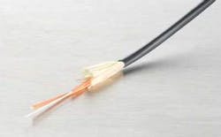
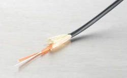
Typical termination into a surveillance camera is with a cable containing two fibers. Normally, an indoor/outdoor flame-retardant tight-buffered fanout cable is used. The cables incorporate dry water-blocking technology and no gels to ensure long-term water-blocking performance. The use of flame-retardant cable eliminates the need for a transition splice when entering a building in accordance with the National Electrical Code.
Historically, tight-buffered cables have not been deployed in outdoor environments because they are more sensitive to temperature extremes and mechanical disturbances than are loose-tube cables. The Insulated Cable Engineers Association (www.icea.net) issued the ICEA-696 Optical Fiber Indoor/Outdoor Cable Standard, which provides cable design and performance guidance that includes a tight-buffered cable option. This is the first ICEA and industry standard that provides guidance on tight-buffered cable intended for deployment in the outside plant as well as the inside plant, and manufacturers are now offering ICEA-696-compliant cables. To date, tight-buffered cables have been designed for deployment only in the benign inside-plant environment.
Outside-plant security camera application spaces include aerial deployment. To meet the demands of that environment, it is essential for tight-buffered cable to be compatible with exposure to ultraviolet (UV) light. The ICEA-696 standard requires that the cable jacket withstand a light exposure test in accordance with ASTM G 155, Cycle 1, except that the exposure is 720 hours at minimum.
Proper selection of UV-resistant jacket materials is critical to conform to this requirement. The use of simple black-colored jacket is not adequate to provide the necessary UV resistance. Unless UV-resistant materials are used, you can expect jacket cracking, brittleness, and failure. These circumstances will compromise system performance.
The fanout cable design provides easy field connectorization of the subunits at the camera, and provides superior pull-out tensile rating versus field connectorizing bare 900-µm tight-buffer fiber, due to the yarns and jacket surrounding the buffered fiber. Field-connectorized 900-µm tight-buffered fibers are almost exclusively used in the back of patch panels where exposure to mechanical forces and reconfigurations is minimal.
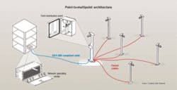
The indoor/outdoor tight-buffered fanout cable is ideal for point-to-point architectures as well as point-to-multipoint architectures. In point-to-point architectures, the fanout cable can be deployed directly from the network operation center to each remote camera site. The cable can be deployed in aerial, duct, and direct-buried application spaces.
For point-to-multipoint architectures, a loose-tube cable or tight-buffered cable with 900-µm buffered fiber (water-blocked, UV-resistant, ICEA-696-compliant) is deployed as a backbone cable from the network operation center to a remote field distribution point. The loose-tube cable design typically consists of multiple buffer tubes that contain 1 to 12 fibers that are stranded around a central member. High-tensile-strength yarns are helically applied around the stranded buffer tubes. Contingent upon the deployment location, a non-flame or flame-retardant jacket is applied.
Making it easy
Recent technology innovations have resulted in a completely gel-free design that contains no filling or flooding compounds, eliminating the time and labor associated with cleaning and terminating fibers. Passive cable transition access to the cameras is achieved through a splice or interconnects of the fanout cable to the backbone cable. In some instances, electronic switches or analog/digital converters are located in the remote distribution box or maintenance hole.
Video systems are being deployed in the enterprise space for security and surveillance applications. Optical-fiber cable connectivity is increasingly being selected by end-users to provide highly efficient and reliable analog and digital video transmission. The high bandwidth and extended distance capability offered by optical-fiber cables, along with its ease of installation, termination, and testing, make optical-fiber cable solutions a favorable option for surveillance network managers.DOUG COLEMAN is manager of technology and standards with Corning Cable Systems (www.corning.com/cablesystems).


