Can your UTP cables take the heat of PoE?
The characteristics of your unshielded twisted-pair cable can help determine the extent to which it will support emerging, higher-current PoE technology.
The convergence of evolving Ethernet-based applications on today’s networks is demanding increased performance from the installed cabling infrastructure and its components. Applications that were once installed over separate, proprietary systems are now being designed to run over the same network as voice and data, using common backbone and horizontal cabling. Some of these applications include security (CCTV and access control), telephony over the Internet (Voice over IP), and even other electronic applications, such as building controls (lighting and HVAC).
The power of design flexibility
An additional trend is the practice of supplying electrical power to these IP-enabled/LAN-connected devices using the structured cabling network. Powering equipment using the physical cabling plant, known as Power over Ethernet (PoE), offers the benefit of centralized control and management of the devices over the installed voice and data network.
The ability to supply power directly to each network element over the data cables increases design flexibility. It is no longer necessary to install separate power cables, conduit, and AC outlets for each device. Examples of equipment that may use PoE include phones, security cameras, and wireless access points.
Once power is supplied over the same low-voltage cabling as voice and data, however, a whole new set of rules and standards needs to be put in place to assure safety and proper performance of the Ethernet-based cabling. Trying to make sense of the continual stream of new IP-enabled products and the associated cable performance differences creates an interesting challenge to system integrators and network installers. Proper planning becomes increasingly important because, without proper planning of the physical infrastructure to prepare for these added IP-based devices, the cable may be pushed beyond its limit and outdate the network before its time. A proactive approach starts with understanding the evolving applications and their effects on the cabling infrastructure from the backbone of the device or desktop.
An evolving environment
To integrate running power over the structured cabling system, industry standards have been created to govern the electrical and physical characteristics for PoE applications. IEEE developed the 802.3af standard in 2003 to define the methodology for the provision of power via balanced cabling to connect data terminal equipment (DTE). The DTE is the device that controls data flowing to or from the computer through Ethernet interfaces. The amount of power specified in this standard is limited by cabling physics and regulatory considerations. Because the 802.3af standard specified compatibility with existing equipment, the transmission guidelines honed in on delivering power over Category 5e, since most networks were running 10Base-T or 100Base-TX over Cat 5e.
Ethernet-delivered power was originally standardized at 12.95 watts; however, many evolving applications will require higher power to run over the existing network. The list includes dual-band access points (approximately 20 watts), pan/tilt/zoom network cameras (15 to 20 watts), IP telephony video phones (15 to 25 watts), RFID readers and access-control systems (up to 25 watts), point-of-sale and information kiosks (13 to 60 watts), and laptops (up to 70 watts).
More power to ya?
In September 2005, the IEEE authorized work to begin on enhancements to existing PoE specifications. The working group, called IEEE 802.3at and commonly referred to as PoE Plus, is developing the next-generation standard. PoE Plus is being designed to operate over existing ISO/IEC 11801-1995 Class D or higher cabling (TIA/EIA Category 5e or Category 6). The proposed standard will increase the powered device (PD) load to a minimum of 30 watts, while conforming to the safety standards, such as ISO/IEC 60950 Safety Information for Information Technology Equipment. Cables must also meet the safety guidelines set forth in the 2005 National Electrical Code.
Increased power will mean an increased amount of current, and increased current in a cable yields a temperature increase of the conductor. Usually, the heat generated inside a cable containing insulated conductors is dissipated via conduction, convection, and radiation through the insulation and jacket. High cable density can lead to added heat within the cable, a situation often found in heavily populated cable trays, equipment rooms, and data centers. The industry trend to install higher-grade cables that use larger conductors, such as Category 6, should minimize the effect of the internal heat.
In addition to complying with safety requirements, cable performance-particularly attenuation-must be considered. If the current flow is very large, the cable may heat to a point that exceeds the maximum cable rating-usually 60° C for communications cabling. Heating the cable affects the cable’s electrical characteristics. For example, insertion loss increases as the temperature rises.
The IEEE has requested technical data and guidance on these topics from ISO, TIA/EIA, and ICEA (Insulated Cable Engineers Association). They are validating existing equations used to calculate heat production on the cable and connectors due to the current, developing new equations that explore the interaction between current and insertion loss, and working to measure heat transfer.
PoE system architecture
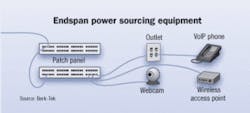
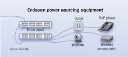
In the PoE schematic (page 25), two types of power sourcing equipment (PSE) provide the DC power to each PD. The PSE is either an endspan or a midspan device.
Power can be added to the Ethernet cable if the switch has a built-in power source known as endspan. These devices often are implemented when a new network is created, and work in 10/100Base-T (Ethernet and Fast Ethernet) channel configurations that use the two transmission pairs (pins 1-2 and 3-6).
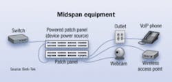
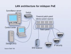
Midspan equipment (see figure, page 26) enables end users to use the existing infrastructure to deliver power. It is placed within the structured cabling system, between the switch and the PD, and sends power down the unused pairs (pins 4-5 and 7-8) to each end device for 10/100Base-T.
PoE midspans offer a cost-effective solution for upgrading the system to IEEE 802.3at. Midspan, when designed correctly, does not require rationing of power among devices, as is found with an endspan switch that requires a larger power-supply device. In a midspan environment, data is passively sent through the device. A single midspan can be used to support multiple PDs.
The two basic types of midspan devices are a powered hub and a powered patch panel. A powered hub (which is not a true hub in the sense that it passively allows data signals to pass through; it does not perform any routing functions such as those found in a network hub) is placed between the switch and a passive patch panel. Patch cords from the switch to the hub are then matched with a corresponding port and patch cord out to the patch panel that subsequently provides power to the PD. A powered patch panel eliminates the hub and is connected directly from the switch to power the end device. Power is provided on the unused data pairs on the cable that is punched down into the powered patch panel.
All IEEE 802.3af devices accept power from either midspan or endspan equipment, even though different pairs are powered. This includes newer products that are designed to support 1000Base-T and higher.
Cabling challenges
As new power-hungry devices surface to take advantage of expanding PoE opportunities, the demand to define “high-power PoE” cable limitations is becoming critical. Ultimately, the cable will be relied upon as the solution to efficiently carry sufficient power, while delivering error-free data throughout the network.
Cables that minimally meet standard specifications may have difficulty supporting both data and DC power simultaneously. With the increase in power, essential electrical operation parameters, particularly attenuation, are affected when the cable’s conductors are heated, especially from the output of the PSE.
Protection of the telecommunications wiring from overheating is currently achieved by limiting the maximum current, which is dependent on the gauge size. As an example, the larger conductor size, such as Berk-Tek’s LANmark-2000 enhanced Category 6, gives the cable a current-carrying capacity of 2.9 amps, compared to the 2.0 amps currently specified for Category 5e.
Ideally, cables with this larger gauge size will surpass performance specifications in characteristics, including insertion loss, crosstalk immunity, and rislience to high temperatures.
With the objective of PoE Plus, which include pursuing the support of operations for 1000Base-T and 10GBase-T while evaluating the effects on cable heating, today’s solution is to install a cable that will provide the lowest insertion loss while maintaining consistent system performance. Larger gauge size and effective pair separation within UTP cables improve their current-carrying capacity and resilience to higher temperatures, resulting in improved performance.CAROL EVERETT OLIVER is marketing analyst with Berk-Tek, a Nexans Co. (www.berktek.com).
