Modeling channel return loss and signal-distortion effects
Thomas R. Russell / Quabbin Wire & Cable Co. Inc.
Higher-frequency signals require examining effects of certain electrical characteristics.
Almost four years ago, Quabbin Wire & Cable Co. Inc. began measuring local-area-network (LAN) channel return loss and studying its echo and distortion effects. Since it began the study, Quabbin has worked closely with most premises-wiring hardware makers, and the program continues today. The information gathered over this course of study, which will be presented in this article, has been shared with the Telecommunications Industry Association (TIA—Arlington, VA) for its benefit and is being presented at the BICSI (Tampa, FL) Summer Conference later this month in Nashville, TN.
About three years ago, the 802.3 Ethernet group of the Institute of Electrical and Electronics Engineers (IEEE—New York City) was defining the chip characteristics necessary to run 1000Base-T on 4-pair unshielded twisted-pair (UTP) copper. The group wanted the protocol to signal adequately on the huge worldwide installed base of Category 5 cabling systems. The IEEE asked the TIA's committee on copper systems to define the baseline electrical characteristics for these Category 5 premises networks, including the common test parameters and also return loss (RL), which was a new test characteristic. That was the first time the TIA's copper systems committee had to define and quantify channel RL. Up to that point, RL was considered unimportant.
What is return loss?
What is RL and why was it ignored up until that point? Return loss is simply signal echo within a conductor pair. It should not be confused with signal crosstalk, which is signal noise between pairs. RL noise echo was ignored for the 10Base-T and 100Base-T protocols because they both use unidirectional signaling, which sends data on one pair and receives data on another. Therefore, echo or RL noise within a given pair never interferes with a receiver. The chipset's receivers do not have to compensate for noise they will never hear.

Gigabit Ethernet, or 1000Base-T in its copper form, is much more complex. To enable signaling at 1000 Mbits/sec on 4-pair UTP copper, the IEEE decided to use all four pairs, implement exotic five-level voltage encoding, and also implement bidirectional signaling. Each of the four pairs would be simultaneously sending and receiving data, with a transceiver chip at each end. With the ends of each pair both sending and receiving, their RL noise mattered because there was now a receiver that could be affected by the echo noise. Also, transmitting more data in the same unit-time resulted in signaling that was more sensitive to all noise sources.
The echo noise produced by RL is relatively easy to understand and the subject of much discussion. However, RL has another effect that is not widely understood in the LAN cabling industry: signal distortion. This distortion not only affects bidirectional signaling protocols such as 1000Base-T, but also causes transmitted pulse distortion in any protocol. It is also especially important for all higher-speed signal schemes such as Asynchronous Transfer Mode (ATM) and 100Base-T, even though those protocols are unidirectional.
A perfect channel would have no RL noise, only signal attenuation. But in the real world, all channels have some degree of RL caused by discontinuities and impedance mismatches within the network. Discontinuities occur at bent or distorted pairs, plug-to-jack physical connections, and the interface between a pair's conductors and a connector. Impedance mismatches are usually within a pair (along its length) or between connected pairs in different cables. All the components in a network channel must be designed to have an impedance of 100 ohms, with little variation or deviation from that target. If a plug and jack or the patch cable and horizontal cable are not closely matched to the 100-ohm target, some of the transmitted signal gets reflected, and RL is created.
RL, in turn, impacts digital signaling by causing the transmitted signal pulses to spread out in time. As these transmitted pulses spread or distort more and more, they actually interfere with, or spread into, adjacent pulses. This is called inter-symbol interference (ISI). Networks with too much ISI have bit errors at the receiver, require data retransmissions, and effectively slow down or even crash. The chipsets for 100Base-T and 1000Base-T are designed to accept a certain amount of ISI and compensate or equalize the distorted signal. But too much ISI overwhelms them.
1000Base-T signal modeling on a Category 5 network results in 104 millivolts of ISI at the receiver, which is a huge noise amount compared to either far-end crosstalk (FEXT) or near-end crosstalk (NEXT). The 1000Base-T model allows for only 2.1-mV residual ISI noise after equalization, which demonstrates why RL and the ISI it creates are so significant for efficient signaling. Early chipsets for Fast Ethernet are even more sensitive to RL and ISI.
Return loss and channel modeling
Quabbin recently demonstrated this RL/ISI distortion effect by mathematically modeling a channel. The advantage of this approach is that once you have developed the algorithm or equation, you can make changes to it and run "what-if" simulations similar to a spreadsheet calculation. The actual equation for channel simulation defines the transfer function of a channel. It includes terms for input voltage, output voltage, attenuation, propagation constant, length, reflection coefficient, and transmission coefficient. It is quite complex and beyond the scope of discussion within this article.
Three different channels were modeled, each having the same physical configuration consisting of a 90-meter horizontal cable, 2-meter equipment cord, 2-meter patch cord, and 2-meter work-area cord.
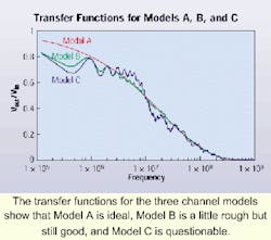
Channel Model A is an ideal or perfect channel, with attenuation but no RL. It had no impedance mismatches or discontinuities. Such a channel would be impossible to physically build except in a simulation. Because there are no impedance mismatches or RL, the curve is smooth.
Channel Model B has small impedance mismatches (only about 2-ohms difference between all cords and the horizontal cable) with very good connections (18-dB RL at 100 MHz). Model B is quite close to actual channel solutions now being sold as "Category 6." Although there is some RL, the curve is quite similar to the ideal model. However, it does show some roughness.
Channel Model C consists of relatively large impedance mismatches. The three patch cords are 108, 88, and 88 ohms, and the horizontal cable is 108 ohms. The connections consist of one at 10-dB and two at 18-dB RL. Model C does not meet the requirements of Category 5E and is probably quite representative of the older channels that meet Category 5 and are now running 10Base-T Ethernet traffic. As expected, Model C's transfer function exhibits more roughness than that found in Model B.
For the purposes of our experiment, we applied an input pulse to each model, converted the pulse equation from time domain to frequency domain, multiplied by the transfer function, then calculated the output pulse (which converted back to the time domain). Thus, it was possible to directly compare input to output of the three models. Again, the calculation is complex.
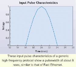
The input pulse has a rise of about 3.4 nsec and a width of about 8 nsec. It is intended to represent a generic high-frequency protocol and is actually similar to a 100Base-T pulse.
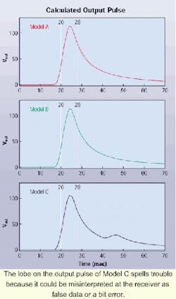
When we modeled the output of these three channels, we found that Model A's output is an ideal pulse that represents a target everyone would hope to approach. The pulse rise-time is good, and the pulse fall-time shows the spread due to attenuation alone. Model B's output is also good and virtually identical to Model A's. However, Model C's output is not nearly as good. There is a lobe in the pulse edge, which occurs well outside the 8-nsec width of the input pulse. The receiver could interpret this lobe as false data or a bit error.
Eye-pattern diagrams
Next, we used the models to generate eye-pattern diagrams, which are often used to determine the efficiency and accuracy of real channels processing complex high-frequency data pulses. We used three-level voltage pulses, which are similar to 100Base-T encoding. Many of the newer network protocols use encoding schemes that simultaneously process data, detect errors, recover timing, and perform other compensatory functions. And many network users are currently migrating to 100Base-T.
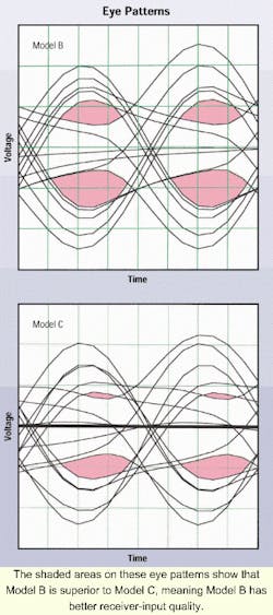
A random data sequence was applied to the transfer functions, and the output shifted in time, generating the pattern. The sizes of the "eye" openings represent the receiver-input quality, with the top eyes being positive voltage responses and the lower eyes negative voltages. Open or larger eyes mean less ISI.
When examining the eye patterns, we see that Model B exhibits a healthy receiver input even though the channel is transmitting a relatively complex protocol. Both the positive and negative eye openings are large, indicating a strong signal input to the receiver chip for processing. Model C's eye pattern is not as robust. The negative voltage eyes are not as open as Model B's, and Model C's positive eyes are almost shut because of the lobe in the output pulse, higher channel RL, and increased ISI.
Room for improvement
The signal-processing chips in network interface cards and hubs must equalize or compensate for the ISI and distorted signal quality. If the channel's transfer function is relatively smooth, this compensation can be accomplished efficiently by using a relatively simple equalizer that is the opposite of the cable's attenuation. If the function is very rough, as is Model C's, equalizer compensation becomes complex, expensive, and inefficient. Simple equalizers cannot fully compensate for Model C's performance, resulting in transmission data errors, clock timing errors, retransmissions, and a slow channel. The complex 100Base-T signaling would process much more efficiently on Model B, and this raises a question: Can Model C be easily and economically modified to make it more efficient as well?
Earlier channel-measurement studies provided strong evidence that RL performance is greatly influenced by the quality of the patch cords used in the channel. What would Model C's transfer function and resulting eye-pattern look like if we mathematically exchanged the original cords for the better cords used in Model B, yet made no changes in Model C's original horizontal cable or connections? Changing patch cords is a relatively quick and economical "fix." In fact, the TIA's telecommunications systems bulletin TSB-95 recommends changing patch cords as the first "fix" if you have network difficulties.
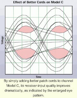
Changing cords is a simple "what if" using modeling simulation, and doing so resulted in an improved eye-diagram pattern. In fact, changing the patch cords improved Model C's pattern to a point where it strongly resembled Model B's pattern. The Model C channel, modified with better patch cords, is now much more robust and efficient when transmitting 100Base-T signals. The chipsets at either end of any pair can more accurately reproduce the transmitted signal with the reduced RL noise and ISI in the channel.
The channel-modeling simulation has shown that channels with large impedance mismatches and large amounts of RL perform poorly at high frequencies. This is true even when transmitting unidirectional protocols such as 100Base-T or ATM, because the chipsets must find the distorted transmission signal in the noise caused by ISI. Bidirectional protocols such as 1000Base-T are even more greatly affected by RL noise. They are degraded twice—first by the ISI and signal distortion, then by echo noise at both ends of each pair.
However, channel modeling has also shown that high-quality patch cords actually improve the performance of legacy or marginal systems. Better cords improve channel RL noise, effectively enabling the signal-processing chips to perform their function faster and more efficiently. Since most LANs worldwide are currently 4-pair UTP Category 5 installations, this relatively inexpensive and easy "fix" will enable many networks to efficiently migrate to protocols beyond 10Base-T.
Thomas R. Russell is vice president of technical marketing at Quabbin Wire & Cable Co. Inc. (Ware, MA). Several white papers covering technical elements in this article are posted at the company's Website, www.quabbin.com/tech_briefs.

