Technology: UTP system performance hinges on connectivity issues
Plugs, jacks, and patch cords must make technological strides before Cat 6 is a reality.
Patrick McLaughlin
In March 1999, the Telecommunications Industry Association's (TIA-Arlington, VA) TR-42 Engineering Committee issued a statement vowing to establish a Category 6 standard that will allow full interoperability and backward-compatibility. Full interoperability means that any Category 6 plug can be used with any Category 6 jack, and the mated pair will achieve Category 6 performance. Backward-compatibility means that if a Category 6 plug is mated with a lower-performing jack-Category 5, for instance-the mated pair will achieve at least Category 5 performance. Likewise for lower-performing plugs and Category 6 jacks.
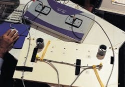
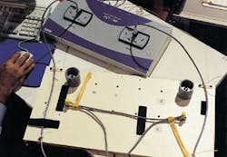
Information generated from this test setup was used to argue that a 1-inch patch-cord bend radius is no more beneficial to system performance than a quarter-inch radius. In tests, cords were wrapped around the gray and yellow jigs to achieve 1- and quarter-inch radii, respectively. Cords were also tested fully collapsed.
At the time of this writing, it had been just about one year since the TIA issued that pledge. How has the TR-42 Engineering Committee progressed since then? For starters, the group finally got Category 5E off its back; in March 1999, Category 5E was still very much a work-in-progress for the group. "One of the real holdups to getting Category 6 done was Category 5E," says Val Rybinski, senior electrical engineer with the Siemon Co. (Watertown, CT), who also serves as document editor for the forthcoming Category 6 standard. "That project consumed a lot of the group's meeting time and prevented us from making progress on Category 6."
Rybinski reports that according to the committee's schedule, a first-ballot review for Category 6 is scheduled for the next meeting, which will be held later this spring. The next step is a process called default balloting. "The goal is to have it approved in November 2000 [two meetings after the first ballot]," she says.
The efficiency with which the group can resolve two technical issues, both related to connectivity, will impact whether the group can publish the standard by its target date. Interestingly, even though both issues are technically oriented, they differ in that one is painfully narrow and exact, while the other appears to be wide-ranging in scope. The "narrow" issue is the de-embedded performance characteristics of modular plugs, and the broad-based issue is patch cords.
De-embedded plug performance
In an unshielded twisted-pair (UTP) plug/jack configuration, the plug is a crosstalk contributor. The jack compensates with negative crosstalk, with the goal of nullifying the crosstalk contributed by the plug. This fact has fostered the idea that plugs and jacks-particularly those from any given manufacturer-are tuned to each other to achieve a given performance level. This condition also holds true for screened twisted-pair cabling but not fully shielded cabling.
The Category 6 standard will be specified to 250 MHz, with positive attenuation-to-crosstalk ratio (ACR) specified to 200 MHz. Attaining the proper tuning of a plug/jack combination at such high frequencies has challenged connectivity-component manufacturers.
Determining the plug's crosstalk contribution requires de-embedding, a test procedure that characterizes both capacitive and inductive effects of the plug, according to Michael O'Connor of Hubbell Premise Wiring (Stonington, CT). O'Connor also serves on the TIA's TR-42.7.1 Connecting Hardware Working Group. "This procedure essentially measures a test plug mated with a modular jack and mathematically subtracts the modular jack's NEXT [near-end crosstalk] loss from the mated connection, leaving a result for the plug."
The tricky part is that for Category 6 products to be interoperable with one another, all Category 6 plugs-and therefore jacks, too-must perform within a certain, yet-to-be-finalized de-embedded NEXT loss, far-end crosstalk (FEXT) loss, and possible other measurement windows. "This will be a significant achievement," O'Connor notes.
Rybinski says manufacturers, particularly those who participate in the TR-42 committee, are well-informed of the performance parameters their products have to meet. "There's some good news in the fact that the performance numbers are available now, which means that manufacturers can make products that comply with what ultimately will probably be the Category 6 standard." She adds that the standards-making group has reached a point where the performance numbers are unlikely to change before publication. "I would estimate that we are 95% complete in specifying de-embedded NEXT," she says, adding that the group is also about halfway toward consensus on a de-embedded FEXT specification.
With Category 6, she says, the performance limits are so tight that FEXT cannot be ignored. However, the de-embedded FEXT figures will probably not be as precise as de-embedded NEXT. O'Connor adds that de-embedded return loss is not out of the question either. "There is talk of a return-loss measurement within the TR-42.7.1 Connecting Hardware Working Group. The TIA has taken initial steps and recently established values for de-embedded NEXT, which will be incorporated into the next draft-Draft 6-of Category 6. These values will be anchored at 100 MHz to establish backward-compatibility with Category 5E but will be specified throughout the frequency range. The range will be much tighter than that specified for Category 5E."
To the left of the patch-cord setup is the LeCroy NEWSLine tester, which evaluates network integrity from the physical layer to the application layer and from the hub to the network interface card.
With the knowledge they have, some manufacturers now are offering products they say will meet the specifications. Many of these products are being marketed as Category 6 component-level-compliant. TIA cabling standards specify component and channel performance. The Siemon Co.'s Rybinski explains, however, that it's not as simple as adding up all the component figures to get the channel figure. "Components can be viewed as building blocks," she says. "If all your components are compliant, then your channel will have headroom because some margin is built into the channel numbers. The idea is to make sure that the end user has a little bit of tolerance." So theoretically, it's possible-and in the field it's almost a certainty-that some installed cabling systems achieve channel compliance even with one or more components that do not achieve component-level compliance.
O'Connor says claims of component compliance cannot be guaranteed quite yet. "As for manufacturers marketing Category 6 component-compliant products," he explains, "there is a risk associated with these claims, as TIA component parameters are continuously being tightened. With the ongoing tests involved within the de-embedding procedure, along with the strong possibility of balance requirements for modular jacks, these so-called Category 6 components should be put under scrutiny."
He also offers some advice for those considering Category 6 purchases: "Caution should be used when purchasing 'component-compliant Category 6 products' for the reasons I described. On the other hand, channel values have not changed and harmonize with ISO/IEC Class E requirements. I would recommend Category 6 solutions to anyone who is willing to pay a premium and test it thoroughly." He adds that as of this writing, most Level III handheld testers available can only measure the basic link, not the channel. "Also," he recommends, "ask your cabling-system manufacturer for independent third-party verification data along with an extended warranty."
Peril of patch cords
"There are risks associated with channel performance without component compliance," Rybinski adds. One risk in particular is that the work-area connection will not be component-compliant. The work-area connection, of course, includes a patch cord. Long considered the proverbial weak link in structured cabling systems, patch cords have historically been the least-quantified component in standards. But all that is changing, especially since the TIA began working toward a Category 6 standard.
Several factors have thrust patch cords to the forefront. First is the tightness of Category 6 channel-performance requirements, which leaves little room for any marginal components. And second, real-world environments can differ greatly from the laboratory environments in which cords are tested.
Analysis by several industry vendors indicates that merely moving a patch cord can change the results of a channel test on a local-area-network (LAN) cable tester. The implications of patch cords' volatility are significant. A mere adjustment of a patch cord's position can potentially cause a previously passing channel to fail, or vice versa.
"These implications are due to return loss," says O'Connor. "Return loss has become an important measurement due to the emergence of Gigabit Ethernet, which utilizes simultaneous bidirectional transmission over each pair in a 4-pair cabling system. There is a patch-cord return-loss procedure written in the newly released TIA/EIA-568A-5. This procedure addresses Category 5E patch-cord performance as well as return-loss variability. A mechanical stress test procedure is also incorporated into this document."
One effort to minimize patch cords' potentially harmful effects is to specify a minimum bend radius for them. But before a proper bend-radius figure is established, several questions must be addressed, such as: Given that channel performance or the assembled patch-cord performance can change by simply moving a patch cord, is the performance difference a result of movement of the pairs within a cord, movement of the contacts in the plug/jack configuration, or some combination of both?
"In a well-designed connector pair, the contact between the plug and jack will not change due to slight movement in the cord," O'Connor says. "The changes may occur at the point where the cable exits the plug body at the strain-relief point, as it is the area of most strain. Another consideration is the bending of cable in service loops, crushing due to traffic or misuse, and other use issues. It should be noted that well-constructed cords with good strain relief will not be as susceptible to these handling constraints. In addition, well-matched systems with additional performance margin are less likely to fail the test due to these changes."
These technical issues were fodder for much discussion at the most recent TR-42 meeting in late February and early March. A presentation to the group offered evidence that a bend radius of one times the cord's diameter is no more harmful to system performance than a four times (1-inch) patch-cord bend radius and can more realistically be achieved in the field. In some cases, according to the presentation, the tighter bend radius increases performance.
Dennis Mazaris of PerfectSite (Sterling, VA) gave the pre sentation and says it is the result of research, laboratory testing, and field analysis conducted over more than a year. Mazaris has a particular interest in the specification of a patch-cord bend radius because he manufactures a product, called PerfectPatch, that is aimed at patch-cord management in the telecommunications closet. The product requires bending the patch cord to approximately a quarter-inch controlled radius-a figure very close to the diameter of many patch cables.
Mazaris says his research is genuine, and takes into consideration standard patch-cord installation practices. Apparently it was enough to convince the TIA group working on the standard, which voted to include the one-times-outer-diameter bend-radius specification for UTP cables in its working document. The bend radius for screened twisted-pair cable is eight times the diameter. As mentioned earlier, however, that document must go through the balloting process before it is finalized, so that bend-radius figure is written in pencil and the standards group has plenty of opportunity to erase and amend, provided that such amendments are justifed technically.
So what can cabling-system end users take from this information? What can they do and not do with their patch cords? And how much consideration will be given to what Mazaris describes as "standard patch-cord installation practices?" The most important response to that concern is that no standard is finalized yet. The November 2000 target may be optimistic, so it might be more than six months before all issues are cleared up and definitive answers are available.
"There are currently outstanding issues inherent to Category 6, which must be addressed prior to ratification," continues Hubbell's O'Connor. "These issues include, but are not limited to, permanent-link requirements, insertion-loss deviation, and balance requirements. In addition to these issues, logistic and editorial problems may surface as the document goes through balloting, with more than 60 companies voting on the document." He adds that the prediction for ratification before year-end is "possible, albeit slightly optimistic."
Workmanship issues
The idea of mandating that a patch cord be configured to allow at least a minimum bend radius can be considered a workmanship issue, and in that sense, it is different from the component and system performance that the TIA most often specifies. However, this will not be the first time that the group has mandated a certain type of cabling workmanship.
Another example is the requirement that the twisted-pairs in a Category 5 cable be untwisted no more than a half-inch during termination and the pairs of a Category 3 cable be untwisted no more than 1 inch. Both the untwist and the bend-radius specifications are intended to ensure system performance, but neither one can be measured individually by a LAN cable tester. So how can an end user be sure they are honored?
"You have to conduct a good visual inspection of the installation," says Don Wright, director of training for Compel (Santa Fe Springs, CA) and a BICSI-certified (Tampa, FL) trainer. He says sometimes installers try to put an added twist into a wire pair before termination, which typically backfires. "The brown pair has the loosest twist of the four," he explains. "Some installers grab the brown pair, give it a twist, then terminate it. That extra twist affects the electrical characteristics. The biggest issue is changing the geometry of the twisted-pair. Anytime you change the geometry, you change the electrical characteristics."
He adds that once installers get used to the proper process, it is rarely a problem. "The half-inch untwist is easy to adhere to once it has been taught. Sometimes installers don't untwist the pairs enough, which can be a problem with the conductors, especially in a BIX installation.
"And typically, when there's a problem with the untwist, that's not the only problem found with the installation. On the other hand, when quality of termination is there, quality is also found throughout the installation."
Wright says the standards process is good for installers and for the cabling industry as a whole, and he reflects on the former assumptions about cabling. "It used to be that if something went wrong in a network, it was assumed to be the cable at fault." That has changed, he says, thanks in part to the standards process: "Through standardization, a consistency is defined with certain parameters so that manufacturers can build products to at least the worst case." And that consistency has helped diminish the assumption that a network problem necessarily is a cabling problem.
O'Connor concludes by reflecting on enforcement of patch-cord bend radius and other workmanship issues. "Patch-cord bending is a difficult issue to enforce," he says. "When a specification is called out by a standard, then the cable manufacturers have to make sure their cords will perform given the particular configurations. On the other end of things, the TIA does not want to place unreasonable restrictions on end users that cannot be followed."
CORRECTION
In our March 2000 issue, the captions for the illustrations on pages 30 and 32 were inadvertently switched. Also in our March issue, in the illustration on page 52, the component labeled "Work-area cable A" should have been labeled "Work-area cable C." We apologize for any confusion these errors may have caused.


