Make the right connection: Bonding a shielded system
Bonding the system to ground helps ensure optimum performance of your shielded system.
by Tom Turner and Robert Dennelly
With the publication of the IEEE 802.3an 10GBase-T standard in 2006, Augmented Category 6 (i.e., Category 6A) cabling systems are being deployed in data centers. Due to the high electrical frequency needed to support 10-Gbit/sec data rates over copper cabling, the mitigation of signal coupling between cables in close proximity, known as alien crosstalk (alien near-end crosstalk or NEXT, and alien equal-level far-end crosstalk or ELFEXT, which is also called alien attenuation-to-crosstalk-ratio at the far end, or AACRF), is critical to meet 10GBase-T performance standards.
Shielded Category 6A links offer clear performance benefits at 10 Gbits/sec by reducing or eliminating the effect of alien crosstalk and providing superior immunity to electromagnetic interference (EMI), such as radio-frequency interference (RFI). But it is important that shielded cabling systems be properly bonded and grounded to ensure the highest level of performance and to protect expensive IT equipment. If shielded cabling systems are not properly designed and/or installed, transmission errors may occur due to unwanted additional noise.
Let’s consider the performance benefits of shielded twisted-pair structured cabling, and answer the following top-of-mind user questions on bonding and grounding best practices:
- Where, and how often, should the shielded cabling system be bonded?
- How can I tell if my existing grounding system is adequate for shielded cable?
- How can I tell if ground-loop problems exist at the workstation, and what can be done about the loops?
Performance benefits of 6A
Copper is the preferred structured cabling medium for most connections in the data center and horizontal links to the workstation due to its easy termination and installation in the field, and cost-effective electronics. Of the available copper cabling types, unshielded twisted-pair (UTP) Category 6A copper solutions are specifically designed to reduce the effect of alien crosstalk by incorporating innovative features into both the cable (such as increased separation between cables and tighter twist rates) and the connectors (such as crosstalk suppression within the printed circuit board).
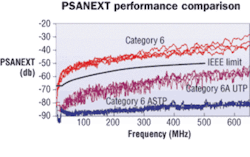
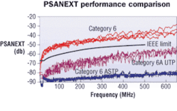
Shielded Category 6A systems offer a different technique to suppress alien crosstalk, using foil and/or braided shielding within the cable to prevent signals from coupling between cables. These screens provide significant margin over IEEE 802.3an specifications for power-sum alien attenuation-to-crosstalk ratio at the far end (PSAACRF), virtually eliminating the effect of alien crosstalk and providing more than 20 dB of headroom over comparable UTP systems. This impact is similar whether the cable contains individual shields around each pair or a single foil around all pairs.
The increased suppression of ANEXT and AACRF by shielded cables also eliminates the need for costly and time-consuming field-testing of alien crosstalk. Further, the foil shields provide superior immunity to EMI/RFI and makes it difficult for unauthorized users to “listen in” by providing a more-secure data environment for such markets as government or such applications as gaming that require strong levels of security.
Importance of bonding, grounding
Although overall integrity of the power and grounding system is crucial to ensure the reliability of all networked equipment, there is often confusion over how to properly ground and bond shielded cabling solutions.
The primary purpose of the grounding and bonding system is to create a robust path for equalization of voltages and for resultant surge currents to return to their source. Lightning, power-system fault currents, circuit switching (motors on and off), activation of surge-protection devices, and electrostatic discharge (ESD) are common causes of transient voltages and electrical surges. Ground loops are a potential disruption to data signals, and develop when a voltage difference occurs in the ground at each end of a cable shield, causing a current to flow through the shield.
To realize the full performance benefits of any structured cabling system, shielded or unshielded, the overall integrity of the bonding and grounding system must be sound. According to standards TIA-942, ANSI J-STD-607-A, and IEEE Std 1100-2005 (The Emerald Book), here are the principles of a properly designed grounding and bonding system in a data center:
- An intentional design-each connection must be engineered and installed to properly handle the anticipated currents;
- Bonds all metallic components to the grounding system (e.g., equipment, racks, cabinets, access floors, ladder racks, cable trays, water pipes, conduit, building steel);
- Visually verifiable and generally arranged for ease of inspection and testing;
- Equalization paths and ports for ESD-protection wrist straps;
- Support for the proper operation of surge protection device for IT equipment and power circuits;
- Electromagnetic compatibility within the data center environment;
- Adherence to all local electrical codes, and listed with a nationally recognized test lab.
In addition, it is recommended that complete system bonding be observed over the entire network to minimize any electrical potential differences. Complete system bonding for any structured cabling system exhibits the following characteristics:
- Electrical continuity throughout the rack;
- Bonds equipment and patch panels to racks/cabinets;
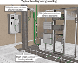
- Bonds each rack/cabinet to the telecommunications grounding busbar (TGB); this may be done via a mesh common bonding network (MCBN);
- Bonds the telecommunications grounding system to the alternating-current (AC) service panels serving the IT equipment in the room; such bonding promotes equivalent ground potential between the IT equipment grounding and the equipment ground of the power system(s) serving the IT equipment;
- Proper bonding and grounding elements (clear covers, ID labels, green-coded conductors) to aid in visual verification of the system.
Best practices for shielded
For shielded cabling systems, the additional step of bonding the cable shield is essential to ensure proper system performance. The foil screen in Category 6A shielded cabling already provides enhanced system performance by preventing unwanted cable-to-cable signal coupling (i.e., alien crosstalk). A properly bonded and grounded shielded cabling system further protects twisted pairs from external noise by carrying induced current along the continuous foil shield of the cable to the transceivers at each end of the cable.
We recommend a 4-step process to properly bond the shield at the patch panel:
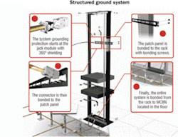
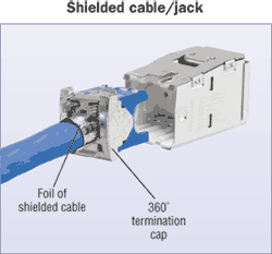
1. Bond all the shielding (foil and/or braid) of the data cable to the shielded jack module, which provides 360° shielding termination.
2. Snap the jack module into an all-metal patch panel to create a bond between the module and the unpainted tabs on the patch panel.
3. Attach the patch panel to the rack using thread-forming bonding screws; the thread on the screws removes paint from the thread holes on the rack, and the serrations on the head of the screws remove paint from the patch panel, creating a high-performance electrical bond between the patch panel and the rack.
4. So long as electrical continuity exists throughout the rack, the last step is to bond the rack to the main busbar or MCBN located under the data center’s raised floor. To ensure long-term integrity of the system, always use compression connectors (not mechanical) so the connection does not loosen with vibration.
Once cabling to the patch field has been bonded, attention can be turned to the rest of the bonding and grounding system. Here are several “best practices” that must be considered during the design and installation of the rest of your shielded structured cabling system:
Best Practice 1: Grounding the cable shield
During installation, a frequently asked question is whether the installer should ground one or both ends of a shielded cable channel. Generally, the cable shield is bonded to the grounded equipment chassis or rack at each access or patch location. In other words, if the IT equipment is grounded, then any shielded cables used to connect equipment to patch panels, or to other equipment, must be grounded.
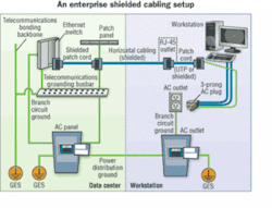
A typical shielded structured cabling channel runs from a switch to the workstation and comprises two patch cord links and the shielded horizontal link. One end of the channel starts in the data center where the switch, patch panel, and shielded patch cord linking them must be properly bonded to the rack. The rack is tied to the telecommunications grounding system, which in turn is bonded to the AC power system.
The other end of the channel terminates outside the data center at the workstation outlet. An issue to considere is whether a shielded cabling link at this outlet location can be properly bonded to a grounding system without inducing a ground loop. A cable shield that is terminated at the workstation may be bonded to the AC ground via connections within the workstation itself, but the outlet AC ground must be at the same potential as the telecommunications grounding system.
Therefore, to reduce the magnitude of such ground currents, all serving AC power systems must be bonded together to the same grounding electrode system. (A building can have only one grounding electrode system, as required by the National Electrical Code.) This approach will reduce any ground voltage differences that may exist either between differing AC power system grounds or between the AC power system ground and the telecommunications ground.
An alternative industry practice is to use UTP patch cords between the outlet and the workstation, effectively grounding only one end of the shielded cable channel in the data center and leaving the cable link at the workstation area ungrounded. The advantage of this option is that the risk of establishing a substantial ground loop current is greatly reduced. This option, however, lowers the level of protection against external noise, such as alien crosstalk, EMI, and RFI, across that link in the channel, thus lowering system performance. It commonly is used only when it is not possible to eliminate voltage differences between ground potentials.
Best practice 2: Ensuring path continuity
To optimize the performance of your shielded (or unshielded) network, you should perform a visual inspection upon installation and on an annual or semi-annual basis thereafter to check for proper bonding and grounding, as well as the overall design of the power and ground system. An inspection that follows a line-by-line work order allows early detection of potential problems, such as: loosened or corroded connections; missing labels; conductors that have been damaged, cut, or removed; and new metallic elements that require connections to the common bonding network described in The Emerald Book.
To facilitate inspection of the grounding system, install connectors, busbars, and conductors in such a way to allow visual verification of the bond. There should be a logical flow as you follow the grounding busbar(s). For example, follow the path(s) from the equipment chassis to the rack, from the rack to the data center grounding infrastructure, then over to the local TGB. The TGB connects to the telecommunications backbone (TBB), or grounding cable, that runs back to the telecommunications main grounding busbar (TMGB), which is bonded to earth ground via the electrical entrance facility and links all the TBBs together. Inspect all splices for proper crimping, and inspect labels to ensure that proper labeling procedures have been followed.
Best practice 3: Testing at the workstation
Once the visual inspection of the data center bonding and grounding system is complete, attention can be turned to the cabling area closest to the end user-the workstation. If a potential difference exists between these two points, a ground loop will form and current may flow within the loop.
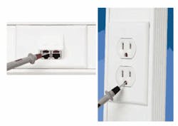
A method for testing whether a ground loop potential exists at a workstation is to use a true RMS multimeter to measure the potential difference between the power outlet ground and the shielded module on the workstation outlet. Position one multimeter probe on the face of the shielded module on the workstation and the other in the grounding prong of the electrical outlet, and check the voltage reading on the meter. If the meter reads less than 1 volt of potential (as described in ANSI J-STD-607-A Annex D) between the module and the power outlet, the endpoint device is expected to operate properly during steady-state conditions.
If the meter reads 1 volt or more, a ground loop problem exists that may cause data errors or equipment damage. To correct this condition, effectively bond the power sources together to the same grounding electrode system.
In summary, it is essential to implement proper structured grounding throughout a shielded cabling system to maximize equipment uptime, maintain system performance, and protect expensive equipment. This is important for all shielded cabling systems, including Category 6A, due to the increased use of this cable type for 10GBase-T transmission. The main advantage of using a shielded Category 6A cabling system for 10GBase-T applications is the dramatic suppression of alien crosstalk; the containment of this noise helps ensure better signal integrity than can be achieved with a UTP cabling system.
But the grounding and bonding requirements of Category 6A shielded cables are more stringent. At the data center end of the structured cabling channels, these requirements include proper bonding of the shielding to the jack, proper grounding of the jack panels, and proper deployment of the grounding and bonding infrastructure within the computer room and building. At the workstation, it is important that the outlet ground is at the same potential as the telecommunications ground.
Grounded for performance
The grounding and bonding system is more than an insurance policy against a lightning strike. It is an active, functioning system that provides protection for personnel and equipment by minimizing the detrimental effects of electrical surges and transient voltages.
By following standard principles and best installation practices, your bonding and grounding system is a critical enabler of high-performance shielded structured cabling solutions to improve network reliability and achieve maximum 10GBase-T performance.
TOM TURNER is business development manager and ROBERT DENNELLY is product liner manager at Panduit Corp. (www.panduit.com).
