Polarity management critical in ribbon-cable designs

A recently ratified TIA specification provides guidance through this sometimes tricky endeavor.
To maximize use of pathways and spaces, LAN campus, building, and data center backbones are migrating to higher cabled-fiber counts to meet system bandwidth needs, as well as to provide the highest connectivity density relative to cable diameter.
Until recently, network designers would specify tight-buffered and loose-tube cable designs for these backbone applications. But in today’s networks, designers are turning to ribbon cable designs because of their ability to meet the design criteria of high connectivity density relative to cable diameter. For example, a 144-fiber unitized tight-buffered cable contains more than 3.5 times the effective area compared to a ribbon plenum cable of the same fiber count. Relative to copper cable, a 216-fiber ribbon plenum cable consumes the same effective area as two to three Category 6A unshielded twisted-pair copper cables.
Ribbon cables, however, require unique polarity design considerations to ensure reliable system performance and to support ease of installation, maintenance, and reconfiguration.
TIA’s ribbon polarity standard
ANSI/TIA/EIA-568-B.1-7-2006 (Commercial Building Telecommunications Cabling Standard Part 1-General Requirements, Addendum 7-Guidelines for Maintaining Polarity Using Array Connectors), was ANSI-approved in January 2006 and facilitates use of ribbon cables.The standard provides serial transmission fiber polarity guidance for systems using MPO (multifiber push-on) optical connectivity.
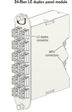
Twelve-fiber array-style connectors, like the MPO, are especially suited for dense wiring requirements in the LAN and data center storage area network (SAN). Pre-assembled and field-terminated MPO-to-MPO connectorized ribbon cables, called trunks, are often used in these locations. Because MPO array connectors are on both ends of these trunks, and the end equipment typically has standard duplex transceiver ports, the trunks are plugged into factory-made breakout furcations (called modules) that transition from the MPO connector to a duplex connector/adapter style.
Each 12-fiber ribbon translates into six 2-fiber serial optical circuits that require polarity management, which can be achieved using one of numerous methods. Like simplex and duplex connectors and adapters, MPO connectors and adapters are also keyed to ensure that proper orientation is maintained when connectors are mated. With MPO connectors, this keying establishes the orientation of one fiber array in one connector relative to the array in the mating connector, but does not ensure that duplex fiber-pair polarity is maintained.
Three routes to consider
The TIA standard includes guidance on three sample methods, identified as Methods A, B, and C. It is important to note that the standard states in paragraph 3.1, “While many methods are available to establish polarity, this Standard outlines sample methods that may be employed.” The word “may” implies that alternate polarity methods are available to accomplish the same result-methods that are not discussed or included in the standard. Thus, the standard shows three examples and recognizes that other valid methods also exist, such as the universal polarity management method that will be discussed later in this article.
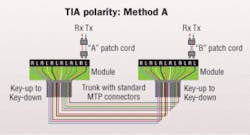
Method A uses a single module type wired in a “straight-through” configuration, and two different patch cords in an optical circuit; one patch cord is straight-wired and the other wired with a pair-wise flip. All components in the channel are mated key-up to key-down.
The TIA standard includes no guidance to differentiate where the patch cord with pair-wise flips should be used and how it should be made so that it is easily recognizable from the regular duplex patch cord “straight-wired.” Because polarity is addressed in the patch cords, the end user is ultimately responsible for managing it.
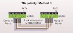
Method B uses a single module type wired in a straight-through configuration and standard patch cords on both ends. The differences are that all components in the system are mated key-up to key-up. When the link is configured in this fashion, physical position #1 goes to physical position #12 on the other end. A module on one end is inverted, so logically (label-wise), position #1 goes to position #1. This method requires advance planning for module locations to identify the module types and location of the inverted module in the optical link, a step that adds complexity to polarity management. Using an MPO connector key-up to key-up configuration does not allow use of an angled polish (APC) singlemode connector.
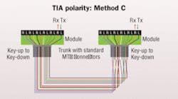
Method C uses a pair-wise fiber flip in the trunk cable to correct for polarity. This enables the use of the same module type on both ends of the channel and standard patch cords. Because polarity is managed in the trunk, extending the links requires planning the number of trunks to maintain polarity. The TIA standard does not include text regarding the ability to migrate to parallel optics for Method C, but parallel-optic capability can easily be achieved with a special patch cord to reverse the pair-wise fiber flips in the trunk.
Universal polarity management
Another method, universal polarity management, is not included in, but meets the intent of, the TIA standard. This enhanced polarity management method uses the same module and patch-cord type at both ends with no inversion or reconfiguration needed to maintain polarity. Polarity is easily accomplished and managed with the module’s internal fiber wiring scheme. The system is mated key-up to key-down.
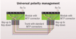
The universal method supports simple concatenation of multiple trunks without affecting polarity. It easily accommodates all simplex/duplex connector types as well as singlemode fiber APC MPO connectors. Similar to Methods A, B, and C, the universal polarity management method easily facilitates migration to parallel optics. Wired modular system components enable fast and simple networking moves, adds, and changes without polarity concerns associated with special polarity-compensating components used in Methods A, B, and C.
Each of the methods works when the rules of that method are followed; however, do not mix and mate component parts from the various methods. This will not necessarily work. The Addendum 7 specifications state that one method should be chosen and used throughout the network.
Evaluate carefully
Numerous ribbon polarity methods are available to consider. Make sure you evaluate each method before implementing to ensure that criteria such as reliability; ease of installation, maintenance, and reconfiguration; as well as the ability to easily migrate to higher-data-rate solutions that may require parallel optics, are addressed and satisfied.DOUG COLEMAN is manager of technology and standards with Corning Cable Systems (www.corningcablesystems.com).

