Patch cords--the missing link in cabling standards
Arlyn S. Powell, Jr.
Installing a cabling system is a little like baking a cake, according to John A. Siemon, vice president of engineering at The Siemon Co. (Watertown, CT). "With a recipe," he said at a panel discussion on unshielded twisted-pair (utp) patch cords that he moderated for bicsi (Tampa, FL) this year, "if you know the ingredients and what to do with them, you should have a fairly good idea of how the result will turn out."
Siemon points out that the Telecommunications Industry Association (tia--Arlington, VA) has established manu-facturing specifications for cable and connecting hardware--analogous to the ingredients in the cake--in its commercial building wiring standard, tia/eia-568a, but "even with standards requirements on components and cabling- system design, variables such as installation make it desirable to also specify the performance of the installed cabling."
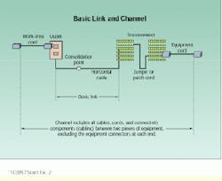
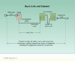
The basic-link and channel specifications contained in telecommunications systems bulletin tsb-67 are the baking directions for our cake. They provide "a description of how the recipe should taste," adds Siemon.
Siemon admits, however, that the recipe analogy may be a bit oversimplified for a technology as complicated as that defining telecommunications distribution systems, so he switches from simile to metaphor, and from recipe to missing link. "Although twisted-pair specifications for cable, connecting hardware, and field testing have been successfully completed," he states, "there remains one piece of the puzzle that has not yet been fitted into place. That piece is the performance of patch-cord assemblies."
The standards-making process for patch-cord assemblies has been under way for several years, but there have been obstacles in the cabling industry to reaching a consensus about how this part of both the basic link and channel should perform. One reason for the delay, says Siemon, is "the complexity of characterizing a plug-cable-plug assembly." Compounding this problem is the fact that plugs as individual components have already been specified, and channel and basic-link performance have been characterized as well. "The challenge is to introduce requirements that do not upset the delicate balance between the existing components and system-level specifications," Siemon adds.
Measuring the performance of patch cords has also been difficult. The only reliable measurement to date, according to Siemon, has called for the terminated connectors to be cut off each end of the patch cord and tested individually, effectively reducing production yields to zero.
Non-destructive testing needed
The first priority, then, is to develop a non-destructive testing method that manufacturers can use to qualify their patch-cord assemblies. Amid Hashim, on the technical staff of Bell Laboratories of Lucent Technologies (Murray Hill, NJ), reported to the bicsi audience that several such methods are under consideration, but each has its pros and cons.
"The de-embedding test method," he said, "is a non-destructive way of measuring near-end crosstalk of unmated patch cords independent of the test fixtures." A patch cord cannot be attached to a test instrument without terminating it using jacks, which then contribute to the near-end crosstalk of the patch-cord assembly. De-embedding characterizes these test jacks separately and mathematically subtracts their crosstalk contribution, leaving a performance value for the unmated patch cord alone.
Hashim states that this test method satisfies the requirements of tia`s PN-2948 committee by being non- destructive, supplying good correlation between testing laboratories, and providing a measurement that can be used to specify patch cords. In addition, this measurement can be translated into pass/fail limits that correlate to how well patch cords perform when mated with Category 5 jacks in an installed link. The committee has established a minimum pass/fail value of 27 decibels at 100 megahertz, and it is looking at a range of values approximately 33 or 34 dB at 100 MHz as the maximum value.
The de-embedding test method, however, involves several steps, which makes it unsuitable for testing factory output. Since it is the only method developed to date that offers consistent test results that are independent of the influence of the mating jacks, a composite approach has been suggested. "A proposal has been made to couple the de-embedding method with a factory production test procedure that is directly traceable to it," according to Hashim. The procedure involves simply using the same uncompensated jacks defined by the de-embedding method to perform a mated patch-cord measurement. Testing laboratories have found excellent correlation--within less than 1 dB--between such a measurement and the de-embedded method. Therefore, if de-embedding is used to select a number of patch cords falling within the pass/fail limit, and these same cords are remeasured using uncompensated jacks, the average difference between the two procedures should fall within one decibel of each other and can be applied as a corrective factor to mated measurements using uncompensated jacks.
The PN-2948 committee is evaluating still a third method of testing patch cords, called the link-measurement procedure. In this procedure, a mated combination of patch cord and a set of prequalified Category 5 jacks are measured. The simplicity of this method, says Hashim, makes it suitable for factory testing, but it has not yet yielded the necessary level of consistency, and it requires the use of test jacks that perform beyond the Category 5 specification. "Additional round-robin testing is needed to assess the degree of correlation between this link-measurement procedure and link performance in the field," Hashim concludes.
Practical advice on testing
Henriecus Koeman, principal engineer at Fluke Corp. (Everett, WA), a maker of cable testers for local area networks, has some advice on the more practical aspects of testing patch cords in the field. "Given a 2-meter patch cord," he says, "you might almost disregard the cable contribution to the overall near-end crosstalk and focus on the near-end crosstalk from the connectors." This is because connectors contribute much more near-end crosstalk than does a cable over a very short span.
In addition, Koeman points out that only the plug connecting the fixed portion of the cable link need be considered, since the definitions of both basic link and channel exclude the jack within the electronic device and the patch-cord plug that attaches to it. Also, he adds, "you must consider the measurement accuracy of your tester."
Koeman suggests measuring the worst-case near-end crosstalk margin over the full range of Category 5 frequencies, from 1 to 100 MHz. It is not adequate, he cautions, to simply measure worst-case near-end crosstalk. "Always test any configuration to the basic-link test limits using a tester with Level II accuracy and require at least 2 dB of margin," he continues. "In that case, you will likely obtain a compliant channel level of performance after exchanging compliant patch cords."
Koeman cautions that, if you are closer to the test limit for the basic link than this 2-dB margin, or if you are close to the channel test limit, "you have to retest after exchanging a qualified patch cord. Even if you just change the orientation of a qualified patch cord, you may have to retest."
End-user considerations
The perspective of the end-user was represented on the bicsi panel by Michael Saunders of Intel (Beaverton, OR). "The size and reduced flexibility of the Category 5 patch cord limits the number that can be reasonably managed in a single vertical field," he observed. "The user can no longer take advantage of the high densities of connections available from the idc [insulation displacement connection] type of field." The largest vertical cable managers accommodate only 400 to 500 patch cords, according to Saunders, leading to the need for larger equipment rooms, in some cases.
Other concerns expressed by Saunders were whether patch cords could be field-assembled, whether they were available in custom or minimum lengths, whether existing field test equipment could be used to measure their performance, and what developments in the standards arena would do to patch-cord costs.
Why do standards continue to be developed?
John A. Siemon of The Siemon Co. (Watertown, CT) cites three main reasons why research and development continue in the field of connecting hardware.
"The first," Siemon says, "is that, in most Category 5 installations, the full bandwidth of the cabling will not be used until months--or even years--after the initial installation. Users of telecommunications services need some level of assurance that the components used in their new `high-performance` cabling systems will be capable of supporting state-of-the-art applications, once they are available and come online."
A second reason, according to Siemon, is that standards groups and providers of new networking applications and equipment need a well-thought-out "design space" for all the transmission parameters that may affect reliable operation of the application. Otherwise, forthcoming network applications such as 622-megabit-per-second Asynchronous Transfer Mode and Gigabit Ethernet (1000Base-T) may not operate dependably in all standards- compliant implementations of Category 5 cabling.
The third, and perhaps most important, reason is that the rapidly expanding base of Category 5 installations is made up of many unique combinations of components, lengths, and installation methods. "This situation," Siemon claims, "has brought new issues to light regarding the characterization and behavior of components and systems." These issues, he adds, relate to both testing methods and ways in which standards-compliant components interact when connected together.
Patch-cord assemblies are a critical part of the basic link and channel, specifications for which are included in telecommunications systems bulletin tsb-67. However, standards for patch-cord performance are not likely to be developed until a non-destructive method of qualifying these assemblies has been developed. Several methods are currently being tested.
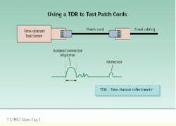
Henriecus Koeman of Fluke Corp. (Everett, WA) recommends a time-domain measurement to determine near-end crosstalk on a patch cable. A time-domain reflectometer can isolate the near-end crosstalk resulting from the local connector, so that it can be evaluated independently of the other connection and reflections outside the area of observation.
This article was developed from papers contained in the proceedings of bicsi`s Summer (1997) Conference. More information on the volume is available from bicsi at tel: (800) 242-7405, fax: (813) 971-4311, or e-mail: www.bicsi.org.


