MPO connector basics and best practices

Given MPOs’ advantages and popularity, it’s worth taking a close look at how these connectors are built and maintained.
By Guillaume Lavallee and Romain Tursi, EXFO
Multifiber push-on (MPO) connectors—also commonly called MTP connectors, as MTP is a brand of MPO-style connector trademarked by US Conec—are increasingly popular because they provide many advantages to high-speed network operators, owners and installation companies. They are used to connect the fastest links that deliver the most sensitive of service and data to customers, enable high-speed interconnects and create redundancy. More and more, telcos are also reconfiguring their central offices into data centers (CORDs) and deploying MPO cables with 12 or, increasingly, 24 fibers. In fact, MPOs are quickly emerging as the connector of choice.
To better understand MPOs, let’s take a quick tour of their design, types, testing and maintenance.
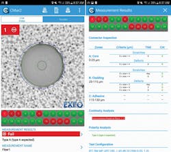
Automated fiber-endface analysis eliminates guesswork, complies with applicable standards, and provides consistent results regardless of experience.
MPO connector design
Color coding—MPO connectors can be color-coded to help you easily distinguish between the different types and specifications. MPO connectors are made for both singlemode and multimode multifiber cables. Singlemode multifiber cable jackets are yellow, and they generally come with angled physical contact (APC) connectors. Because yellow represents either OS1 or OS2 specifications, it’s important to read the cable specifications carefully.
Multimode multifiber connectors have flat ferrules (also referred to as PC or UPC), and the recommended cable jacket colors are aqua for OM3 and OM4, and lime for OM5. However, having one color (aqua) for two different specifications can be confusing. That’s why some manufacturers introduced Erika Violet-colored connectors for OM4, to distinguish them from aqua OM3.
Connector types—Each jacket houses multiple fibers that are also color-coded based on a common standard. The most common type of connector is the MPO-12, which has one row of 12 fibers. Higher-density connectors also exist, composed of several rows of 12 fibers (e.g., 24, 36, 48). More and more, CORDs are using the MPO-24.
The MPO-16 also exists on the market, made up of one row of 16 fibers. Additionally, the MPO-32 is made up of two rows of 16 fibers each.
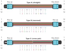
Illustrated here are the three standardized fiber-polarity types: Type A (commonly called straight-through), Type B (commonly called inverted), and Type C (commonly called twisted-pair).
Male and female connectors—Unlike single-fiber connectors, which are all male, MPO connectors can be male (with pins) or female (with corresponding guiding holes). Mating only male connectors with female connectors is primordial to avoid damages (male-on-male) and ensure continuity. The role of the alignment pins is to ensure that fibers are facing each other perfectly.
Connector key—MPO connectors have a key on one side of the connector body. When the connector key faces up (referred to as “key up”), the positions of the fibers within the connector run in a sequence from left to right from position 1 (P1) to position 12 (P12). For MPO connectors with multiple rows, numbers also follow from top to bottom, i.e. P1 to P12 on the first row and P13 to P24 on the second row.
MPOs with 8, 12 or 24 fibers have a connector key in the center. The key is located offset to the left for MPOs with 16 or 32 fibers.
Besides helping to determine the fiber positions, the key also ensures that the connector can be inserted only one way into an MPO adapter or transceiver port.
For MPO APC connectors, the “peak” formed by the 8-degree angle will be on the same side as the key.
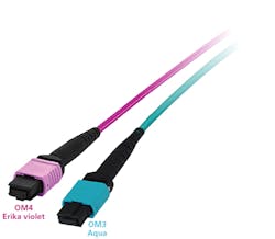
Some providers of MPO-terminated cables use Erika violet colored jackets for OM4 cables, to visually differentiate them from OM3 cables, which are colored aqua.
Essential MPO tests
There are three essential tests you should always perform to ensure the quality of your link: 1) polarity-type validation, 2) continuity confirmation, and 3) inspection.
Polarity—Polarity simply refers to the way fibers are arranged inside the cable. There are three types of fiber polarity.
- Type A (or straight-through method): The fiber located at position 1 (P1) on one end also arrives at P1 on the other end.
- Type B (or inverted method): The fiber located at P1 on one end arrives at P12 at the other end.
- Type C (or twisted pair method): The fiber located at P1 on one end arrives at P2 on the opposing end, P2 arrives at P1, and so on for each pair of fibers.
Type A and B are the most common types of polarity used in data centers and CORDs while Type C is more typical of duplex applications. However, no one polarity type is better than another. Knowing which is appropriate depends on your architecture’s design. Different equipment manufacturers or applications might require different polarity types.
Each element in an MPO system—trunk, adapter, and patch cord—is individually classified by Type A, B, or C and contributes to maintaining polarity.
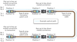
Mating adapter types and polarity—The Type A adapter will mate key-up with key-down connectors, transmitting the signal from fiber 1 in the first cable to fiber 1 in the second cable. A Type A adapter will maintain the polarity.
The Type B adapter will mate both key-up to key-up connectors, transmitting the signal from fiber 1 in the first cable to fiber 12 in the second cable. A Type B adapter will reverse the polarity. Type B adapters apply only to multimode flat connectors, as it would be physically impossible to mate two APC connectors key-up to key-up; they can only mate key-up to key-down to match their angles.
Connectivity method—Each individual MPO element (trunk, adapter, patch cord) is classified by type (A, B, or C) and contributes to maintaining the required polarity so that the right transmitter communicates with the right receiver. But when referring to the end-to-end system, standards refer to the “connectivity method,” which can also be A, B, or C. This should not be confused with the type of each individual element. An A, B, or C connectivity method corresponds to the type of the MPO trunk cable only.
For example, a Method A connection for end-to-end parallel signals will use 1 Type A trunk, 2 Type A mating adapters, 1 Type A patch cord on one end, and 1 Type B patch cord on the other end.
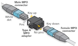
Shown here is a “key-up-to-key-down” mating setup for MPO connectors. This method is used to maintain fiber polarity.
Importance of polarity validation—Why is it important to validate polarity? Your main goal is to make sure the right transmitter (TX) goes to the right receiver (RX). To accurately send and receive data, it is critical that MPO connectors be properly aligned and mated. Bad coupling will impede signal transmission, as the signal could be sent in the wrong direction.
It’s also important because a single cable with a polarity type different from the rest can change the polarity of the entire link. For example, if all your elements are Type A (cable, mating adapters, etc.), but one element is Type B, then the whole link becomes Type B. As a rule of thumb, Type A elements maintain the polarity, while Type B elements will reverse the polarity.
Moreover, when working with a fanout cable, it’s important to be aware of polarity to make the right connections, or you could end up with a different polarity type.
Undiagnosed polarity issues increase capex and work for technicians (i.e., opex). Technicians may unnecessarily rip and replace expensive short-distance MPO patch cords they falsely believe are faulty, but in fact did not have the correct polarity type. If polarity issues are not corrected before turn-up, then it’s a frustrating and tedious guessing game to try to pinpoint which cable connections have polarity problems after they have been installed.
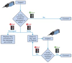
This flowchart walks a technician through the process of inspecting, cleaning if necessary, and reinspecting fiber ferrules, before connecting.
Choosing tools that can validate and clearly identify polarity is essential. Ensuring accurate polarity for MPO fiber array cables is a big deal, and can be complicated to manage due to multiple polarity schemes available for these connectors, and polarity flipping during connection and installation. It becomes even more complex with new flexible MPO connectors that allow field reconfiguration of polarity and gender. Polarity validation is proving especially critical with these new MPO connectors that enable polarity reconfiguration in the field. Be sure to equip your team with solutions that can validate both 12- and 24-fiber cables to avoid unnecessary capex.
Continuity confirmation
Confirming the continuity of a link ensures that there is no break, and that light travels properly all the way to the end of the link under test. It’s a quick validation test that, when done during installation, can save a lot of time in potential troubleshooting later.
Inspection and cleaning—Considering that 80 percent of fiber-network problems are due to dirty connectors, and the number-one cause of network failure is contaminated connectors (according to NTT Advanced Technology research conducted in 2010), it goes without saying that inspection and cleaning are critical.
Having to disconnect an important link to clean or fix it can have a negative impact on the service provided. It’s time-consuming, and more importantly, it can be easily prevented.
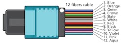
The fibers within a multifiber cable are color-coded as shown here, in accordance with the scheme spelled out in ANSI/TIA-598-D.
With MPO connectors, inspecting and cleaning is particularly important because each port represents a potential point of failure. Additional fibers create more surfaces, which means there is a higher risk of contamination and failure. Bad connectors are a significant cause of loss, and the impact is ever greater for MPO links in which a single dirty or damaged connector can affect as many as 12 or 24 fibers.
What’s more, to guarantee that your network is futureproof and can meet the ever-increasing demand for bandwidth, it becomes crucial to ensure connectors are in good condition. With all the different types of connectors on the market, having a single tool to inspect all types of MPO cables—including multimode or singlemode fibers, APC, UPC male (pinned) and female (unpinned) connectors—can greatly simplify network testing.
How to clean MPOs
The method for cleaning MPO connectors is to inspect, clean, and reinspect.
Inspect—Always inspect the connector first. You don’t need to clean a connector if it’s already clean, as cleaning it might actually make it dirty. This is especially true for MPO connectors, which are highly sensitive. For example, for an MPO-24, dirt from the first row could potentially migrate to the second row while cleaning.
Make sure to inspect both mating connectors, as residue from a dirty connector will transfer to a perfectly clean connector once they mate.
High-performance inspection tools and solutions on the market are better than ever. They allow you to do the following.
- Inspect single-fiber and multifiber cables using the same tool by simply switching the adapter
- Take advantage of a slim design to easily access recessed connectors and dense panel settings
- Get an automated analysis of all fibers or multifiber cables and obtain a clear pass-or-fail result according to your testconfiguration
Clean—If the connector is dirty, first try the dry method. If the dry method fails to remove the dirt, try the hybrid cleaning method, which involves using a solvent.
Reinspect—Always dry your connector after using wet cleaning tools and always reinspect the connector. Simply looking at an image to determine if a fiber is clean can be difficult and subjective. Automated analysis makes testing easy, eliminates guesswork, complies with standards and provides consistent results for all technicians regardless of differences in experience or training. And, by generating a report of your results, you make sure to leave a record of testing and avoid unnecessary troubleshooting in the future.
In sum, with MPOs quickly becoming the connectors of choice, it’s important to know how to gain full advantage of these powerful cables. Understanding how they are configured, choosing the right testing tools, and making sure your cables have passed the three essential MPO tests—polarity, continuity and inspection—are critical to turning up and maintaining efficient links.u
Guillaume Lavallee is product line manager with EXFO. Romain Tursi is product specialist with EXFO.

