Innovations in cabling large-scale data centers

Advancements in fiber-optic cable and connectivity accompany new design and installation practices.
By Dieter Studer, R&M USA Inc.
Cabling large-scale data centers should be called “fibering.” The demand for fiber in data centers is ever-increasing, as the public’s hunger for more bandwidth and electronic services grows. Today’s hyperscale data centers rely on fiber to handle their external and internal traffic. The fiber industry is having a hard time keeping up with the demands of today’s Tier 1 players.
Demand for cloud services has spurred fiber and connectivity development at an unprecedented pace. Innovations in cable design, fiber construction, and connectivity are rapidly occurring. Product lifecycles have changed from years to often several months. New installation practices have challenged designers and installers. This high rate of change has paved the way for a very dynamic and interesting field.
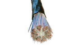
High-fiber-count cables, like this 3456-fiber cable, are commonly used in large-scale data centers today to handle extreme computing needs in limited pathway space.
Innovations in cable design and fiber construction
Fiber optics is the preferred transmission media in today’s data centers, and fiber cable technology is rapidly changing. Just a few years ago, an 864-fiber cable was considered a very large trunk. Today, an 864-fiber cable is a small lateral inside of a data center. Common fiber counts today include 1728, 3456, and 5184. Cables with 6912 and 7776 fibers are on the horizon.
Cable size and the lack of duct space has forced manufacturers to develop smaller cables. Innovations like rollable ribbon have allowed more fibers to be packed inside of a cable and to eliminate some of the loss problems with bending a flat ribbon. Most cables today are dry blocked; gel water block in a cable takes up too much of the precious space. Manufacturers have moved to 200-µm buffered fibers to allow for 30 to 40 percent more fiber in a cable. Cables with slotted cores or with little or no bundle separation have appeared. Innovative designs that repackage flat ribbons into a smaller diameter are appearing. Duct space is so valuable that a data center may remove a recently installed 1728-fiber cable and replace it with a 3456-fiber cable of the same diameter.
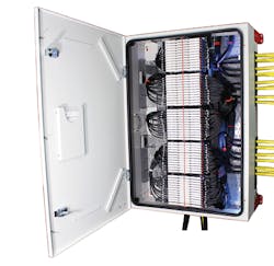
This stackable, wall-mountable building entrance facility cabinet accommodates 23,040 splices.
Innovations in connectivity
Data center operators are figuring out different ways in which fiber can be brought into the facility. Indoor singlemode demarcation is trending. Street access and traffic control is not necessary if a high-fiber-count cable lands inside a building. This scenario also tends to be more secure and tamper-proof. Indoor-rated cables can radiate from this cabinet and go directly to the top of the rack. Horizontal wall space often is limited in these applications. Building entrance facility cabinets are now designed to be stacked vertically to allow for more splice capability. Rethinking how to manage cable, and routing it to splicing cabinets, has made suppliers redesign their offering to meet today’s trends.
Rack space inside the data center is valuable, and high-density panels are now commonplace. Just a few years ago, a common fiber patch panel would be a static 4U offering containing 144 fiber terminations with SC duplex or 288 fiber termination with LC duplex adapters. Many manufacturers have developed high-density offerings that employ slides and special patch cables to allow access to the ports. Panels with up to 240 fiber terminations for LC duplex per 1U have been introduced. These panels rely on MPO trunks to an LC breakout module and slide-based high-density fiber patch panels. Some users have bypassed the use of LC duplex terminations in favor of using MPO ports.

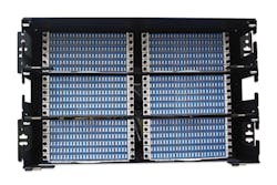
High-density patch panels employ slides and specialized patch cables that accommodate 120 LC terminations (240 fibers) in a single panel.
To reach this high port density, panels are designed with sliding or swing trays. The cable slacks are captured in a cabling manager that ensures the safe movement of the sliding tray for maintenance or extension.
Considering the given location conditions, data center infrastructure managers may evaluate static fiber distribution units with a lower port density. Static panels are generally fed by high-count fiber trunks that are ribbon-spliced within the unit to pigtails going to the ports.
Because the trunks are spliced within the panel, cut-to-length preterminated MPO trunks are not required. Plus, these static cabinets can be used as fiber distribution units (FDUs). An incoming cable into the data center can be terminated into it without having to transition at the main point of entry (MPOE). This is useful if the cable is run in metal conduit, if the cabinet is less than 50 feet inside of the facility, or if the incoming cable is an indoor/outdoor design.
New installation practices
An argument against splicing into a fiber management system is that it requires specialized skill and a ribbon splicer. This argument was more relevant in the past; if a contractor does not have the equipment and skill to terminate, they should not be doing a high-profile job. Testing is still required in both splicing and installing MPO trunk scenarios. Ribbon splicing may be required when installing trunks to make repairs.
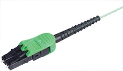
LC patch cords like this one are used in high-density panels with up to 240 fiber terminations in 1U.
Working with large-count rollable ribbon cables and panels requires different craft skills and equipment. When breaking out a large-count cable, technicians need to be more careful, organized and aware of what they are doing. It is easy to mix up different fiber bundles when breaking out a 3456-fiber cable. A damaged fiber during breakout often requires the technician to start over. Some companies have developed tool-less fiber bundle sheath removal to help eliminate this problem. Once the fiber bundles are identified, they need to be furcated with a protective sock or tubing. These furcated fiber bundles need to be housed in a breakout kit, which will keep them protected from being twisted or kinked. Labeling of the fibers, furcated bundles and splice trays is necessary for a quality job.
Working with large-count cables in data centers requires different approaches. An installer will need more launch boxes and test cables. A damaged test lead needs to be replaced immediately to meet deadlines. The installer may consider using a fiber-optic switch in conjunction with their OTDR and OLTS to test MPO terminations. Due to the large quantity of ports to test, often additional test equipment and personnel are required.
This static fiber distribution unit, with 864 fiber terminations in 6U, generally are fed by high-count fiber trunks that are ribbon spliced within the unit to pigtails.
Many data centers do not allow recording devices to leave the facility. A piece of test equipment may have to be left on-site after the job is complete. Test equipment with a cloud interface is prohibited in many facilities. A solution to this problem is for the test equipment to remain on-site upon completion of the job. This creates calibration issues, and it drives up the job cost. A partial solution may be to leave the test equipment mainframe and to remove the optical heads, which contribute significantly to equipment cost.
Traditionally, fiber installations are bidirectionally tested with an OTDR and OLTS. Due to security and time restraints, some data centers have elected to use patch panels prestubbed and pretested with a high-count fiber pigtail. This allows the installer to install a cabinet in a rack and to pull the high-count fiber pigtail to a different location outside of the secured area to splice to an incoming trunk cable. This eliminates splicing or MPO termination time on-site in the secure area. Testing usually is not performed at the secure location unless a problem is encountered. OTDR testing is performed from the non-secured end, which is spliced to the trunk cable.
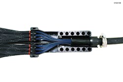
This high-count fiber breakout kit, for up to 7776 fibers, protects furcated fiber bundles from being twisted or kinked.
Splicers for 200- and 250-µm fibers
Specialized fusion splicers are required for splicing today’s high-count cables. As cable technology advances, installers will have to deal with flat ribbons, rollable ribbons, 200-µm buffered fibers, and splicing 200-µm ribbons to other 200- or 250-µm ribbons. This will entail specialized fusion splicers for handling the 200-µm-to-200-µm and 200-µm-to-250-µm ribbon splicing. Different heat strippers and ribbon fiber holders will be required. Equipment purchase is the easy part of working with new cable designs; finding the right personnel and training them tends to be more difficult.
A patch panel with a prestubbed and pretested high-count fiber pigtail allows the installer to install a cabinet in a rack and to pull the high-count fiber pigtail to a different location to splice an incoming trunk cable. This method eliminates splicing or MPO termination time on-site.
Transmission speeds and formats are changing the way fiber is managed in today’s data centers. Many systems use parallel-optic transmission to reach such speed. For instance, some 100G multimode systems require 20 fibers of a 24-fiber MPO connector port. Other systems use higher-speed modulation and wave-division multiplexers to add additional traffic onto fewer fibers.
Installers of today’s data centers will deal with many new technologies and techniques. The cloud, which these facilities support, will continue to grow. Installers who are current with these technologies will realize that there are many opportunities. Data center operators are also looking for organizations that can support their growth.u
Dieter Studer is marketing manager for R&M USA Inc. (www.rdm.com)

