What you need to know to transitioning fiber-optic interconnect from 10G Ethernet to 40G or 100G Ethernet
Accelerated adoption of 40G and 100G fiber-optic Ethernet prepares for exploding data infrastructure demand.
By Dustin Guttadauro, L-Com Global Connectivity
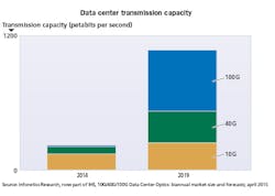
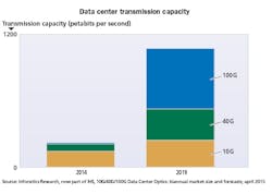
In preparation for the extremely high throughput and low latency demands of upcoming 5G and data infrastructure applications, technologies leveraging 802.3 Ethernet standards for 40G and 100G over fiber optic have seen a steep rise in adoption. Moreover, the implementation of 100G fiber optic Ethernet appears to be outpacing even 40G fiber optic Ethernet for new datacenter and routing applications. Though extremely fast, these technologies come at a time where network complexity is reaching an apex. This article will provide background covering 40G and 100G Ethernet, according to the IEEE 802.3 standards, share updates on market trends and adoption of 100G Ethernet technologies, and highlight upcoming advances in high-speed interconnect.
Feasibility of 40G as data center interconnect
While 100G and beyond is the next major milestone in hyperscale data center speeds, 40G may yet still have longevity in the industry. Traditional enterprises with tier 2 and tier 3 datacenters that have lower density requirements and smaller budgets can reliably leverage the 40G architecture with 10G service speeds as the current building block. Still, as service speeds increase from 10G to 25G, the transition to 100G may come more rapidly with four 25-Gbit/sec lane rates.
Terabit Ethernet—Major 100G technology contributors are seeing a significant rise in 100G revenues as massive 100G deployments are being rolled out by large telecommunications conglomerates with the transition to the 5G networks. This increase in demand for high speed photonics is additionally driven by massive web 2.0 companies as they scale up data centers. The increasingly high bandwidth demands on hyperscale data centers and new network architectures for wireless networks are propelling the groundwork for Terabit Ethernet speeds. Naturally, traditional enterprises will eventually follow the trend leaving a shorter window of time for 40G to thrive.
Building blocks to 100G—Data centers are increasing their data rates with servers migrating from 10G to 25G along line rates. These can be seen with the 40G QSFP+ optical transceivers shifting towards the newer QSFP28 transceivers for short range (SR) routing applications below 100m. The CFP/CFP2/CFP4 transceiver form factors also see an increase in demand for long reach (LR) applications beyond 10km. The growing data center size can at times be limited by the parallel multimode fiber (MMF) reach of 100-150m where singlemode fiber (SMF) cables have been adopted as a solution. The wide demand for 100G optical transceivers is driving advancements in optics, high speed lasers, and 100G integrated circuits (ICs), which can allow for the price of 100G equipment to trend downwards over time.
Direct attach cables (DAC) vs. active optical cables (AOC)—Often leveraged in data centers with 10G SFP+ up to 25G SFP28 based switches, copper-based direct attached cables (DAC) can offer solutions for short link distances between servers and top-of-rack (ToR) switches, storage-to-switch, or switch-to-switch connections (<5m). Active DACs have the advantage of a low power consumption of ~500W and cost-effectiveness while a low power AOC stands around 0.8W of power consumption. Still, the DAC has the disadvantage of being susceptible to electromagnetic interference (EMI). While this may not be an issue in a relatively noise-free environment as the twisted shielded pair innately cancels out common mode noise, a data center with power equipment and other noise sources can cause latency or even failures. Active optical cables (AOC) have begun to replace passive and active DACs as the cost for optic cabling has decreased allowing for data centers to switch to this optical interface. Switching to optics also allows for higher bandwidths as they are able to support 40G and beyond more readily at long link distances. A 100G copper link can be too short for server-to-leaf switch connections.
Singlemode vs. multimode
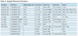
MMF cabling leverages multiple fiber strands for individual optical lanes. Each strand has a core diameter that ranges from 50 to 100 microns and allows multiple modes of light to propagate. MMF variants such as OM3 and OM4 offer options depending upon the link distance and budget of an operation. While the OM3 and OM4 cables are compatible with one another and operate with the same connectors, transceivers, and terminations, the OM4 is better constructed with nearly double the bandwidth (4.7 GHz), lower optical attenuation, and less modal dispersion allowing for longer link distances as shown in Table 1. While the MMF cable allows for high bandwidth and high speed communications, it is limited innately by its design. At long distances the signal integrity is compromised by modal dispersion of the propagating light. This scattering of light into varying paths greatly degrades performance beyond short reach (100-150m) applications. Still, with data center transceivers accounting for nearly 65 percent of the overall 10G, 40G, and 100G of the optical transceiver market, MMFs can have utility as DCI for their functionality up to 150m. Generally, applications that require fiber optic networks to reach beyond 1 km, such as in intra campus/ enterprise/data center routing, must then leverage SMF cabling.
While there is a window of time for 40G to be of utility, the outlook for 100G is brighter, as the cost of the technology is steadily decreasing with the increase in its adoption.
A SMF cable consists of one glass fiber whose core is 8.3 to 10 microns in diameter allowing for only a single mode of light to propagate. The lower power loss allows for data to transmit over longer distances, which make them the prime choice for long reach and extended reach applications. While the SMF cables themselves are only marginally more expensive than MMF cables, the MPO style connectors that are often paired with MMF cables (100GBASE-SR4, 100GBASE-SR10) are more pricy than the standard LC connector often used with SMF cables (100GBASE-LR4).
The main difference in cost is in the optical transceivers as multimode fiber cables can be used with less-expensive light sources such as less precisely aligned vertical cavity surface emitting laser (VCSELs), whereas SMF cables require more coherent laser light sources such as Fabry-Perot (FP) and Distributed Feedback (DFB) lasers. Singlemode optical transceivers are therefore more expensive than their multimode counterparts.
This price difference only becomes more pronounced as speeds increase. For this reason, many traditional enterprises that are leveraging 10G/40G speeds use MMF for links from top-of-rack switches to spine switches while links between spine switches use SMF. Still, as the data rate increases, the transmission distance for MMF decreases rapidly so larger data centers such as Microsoft plan to use only SMF for all future data centers.
Coherent vs. direct detect
There is much talk of the QSFP28 transceiver fast becoming the universal data center form factor since it is smaller, more cost-effective, and consumes less power than its 100G CFPx counterpart [Refer to Table 2]. Still, the larger CFP-DCO (Digital Coherent Optics) transceiver has a built-in high speed DSP (digital signal processing) chip that mitigates chromatic and polarization mode dispersion (CD/PMD) across the photonic line to eliminate the need to insert dispersion compensation modules (DCMs). This extends the reach of the transceiver (>1000km) to serve long haul applications and effectively lessens the complexity in designing switches as vendors do not need to install additional DSP (digital signal processing) chips to their equipment. Vendors also distribute CFP-ACO (Analog Coherent Optics) where the DSP is on a separate PCB to which the transceiver is plugged. This offers a more economical solution for metro carrier applications (>80km). The DSP chips installed with the CFPs also provide high-gain soft-decision forward error correction (FEC) extending the reach of each individual modules as well as spectral shaping to allow for a more densely distributed network.
Single-wavelength pulse amplitude modulation (PAM4) and discrete multi-tone (DMT) are two direct-detection based modulation schemes that break away from the traditional binary non-return to zero (NRZ) modulation for 40G/100G applications with nearly double the bandwidth to enable longer link distances. The PAM4 modulation has already been adopted by IEEE for many of the upcoming 400G proposals. While the direct detect solution does require additional amplification and DCMs for reaches beyond 5km, the cost-effectiveness, size, and moderate reach allows the QSFP28 optical transceiver with PAM4 modulation to potentially serve a unique niche in the industry for long reach intra data center interconnect (DCI) up to 50 km, where it may not be cost-effective to add the advanced optics in coherent devices.
Increasing faceplate density
The overall increase in network capacity requires an increase in faceplate density as the platform cannot feasibly get larger. This can be accomplished through higher bit rates, more integration of the photonic and electronic circuitry, or smaller pluggable form factors. Smaller form factor pluggables can accomplish much in the way of increasing density. Currently the QSFP28 can already yield a 3.6 Tb capacity with a 36 port single rack unit (RU). Additionally, the CFP4 optical transceiver is more than 10 percent smaller than the CFP while consuming a quarter of the power at 6W. Going beyond this generally requires advancements in the optics and their respective ICs.
200G/400G pluggables—One solution to increasing faceplate density has been to decrease the size of the current QSFP28 pluggable, this effort has led to the µQSFP transceiver that can support four electrical channels at up to 28 Gbits/sec. This allows for a 33-percent increase in density with up to 72 ports (up to 7.2 Tb capacity) per RU. Another variant of this pluggable is the double density QSFP (QSFP-DD), an upcoming MSA form factor that can support up to 200G/400G with 25G or 50G over 16 lanes. It is boosted to be the smallest 400G module where a full 36 ports of these on a single rack unit can provide 14.4 Tb of bandwidth. The CDFP is the first 400G form factor with a slightly larger pitch than the CFP4 at 32mm to support 16 lanes at 25 Gbits/sec—a single RU can deliver over 5 Tbits/sec. Essentially the same size as the CFP2, the CFP8 transceiver supports eight 50G lanes for 400G capability enabling up to 6.4 Tb/s in a RU [Refer to Table 2].
Many of these newer optical transceivers require the standardization of a 16-fiber and 32-fiber MPO connector. The MPO connector has evolved from a single row 4 to 12 fibers to 2 to 6 rows of 12 fibers to meet the changing requirements of 10G, 40G, and 100G applications. Often used with the QSFP28 transceiver, the 12-fiber MPO uses 8 total fibers with 4 lanes each for transmitting and receiving data at 25 Gbits/sec. The 24-fiber MPO that is often used with the CFPx transceivers, uses 20 total fibers with 10 lanes each for transmitting and receiving data at 10G. The 16-fiber and 32-fiber MPO connectors is yet another progression for 400G with 1 to 2 rows of 16 fibers.
Photonic integration—Photonic integration essentially combines multiple photonic functions on a single integrated circuit (IC). Also known as a photonic integrated circuit (PIC), this is a key enabling technology for fitting both optical ICs and electronic ICs into increasingly small form factors and standards. Substrates such as Indium Phosphide (InP) with its extremely high electron mobility allows for the fabrication of high frequency laser-modulator chips, splitters, waveguide, multiplexers, and a number of other optical building blocks. Furthermore, multi-project wafers (MPW) can include hundreds of different PIC designs monolithically allowing for further integration. The emerging Silicon PIC (Si-PIC) technology is another choice of substrate that can leverage the decades of fabrication experience for traditional CMOS ICs potentially making this a more economical and scalable option than some III-IV semiconductors.
COBO vs. pluggable—While PICs allow for increasingly smaller pluggable transceivers, they also enable onboard optics where the optics are moved from the front plate and onto the line card closer to the application-specific IC (ASIC). The consortium for onboard optics (COBO) is an effort leaded by Microsoft to standardize the mechanical, optical, and electrical form factors for PCB-mounted optical modules in order to create uniformity across vendors. The quest for increasing the capacity of data center equipment can come with serious thermal management issues. For instance with a power capacity of 12W, the reliability of the QSFP-DD pluggable can potentially degrade over time. This has led to the demand to move these modules to the PCB with the network switching electronics and COBO is already target the end of 2017 to complete the specification.
The transition to terabit data rates requires a subsequent upgrade in the building blocks of the networking technology. This increase in speeds can limit the effective range that passive and active DACs have, leaving many data centers to stick with MMF and SMF cabling. Depending upon the link distance of the application, the transceiver technology and subsequent cabling may change. Long haul applications generally require more complex and costly coherent transceivers and SMF interconnect in order to preserve phase information after electro-optic detection. The more economical direct detect pluggable transceivers are sufficient for short reach DCI with MMF, while modulation schemes such as PAM4 and DMT are an affordable option for longer reach intra-data center applications. The newly proposed smaller pluggables can change the thermal management and thus reliability of the networking equipment, potentially opening a window for the standardization of onboard optics where PICs are a key enabling technology. The future of data networking involves a delicate balancing act between integration and standardization in order to avoid proprietary solutions that can lock companies down while steadily rising the capacity of the networking equipment.
Dustin Guttadauro is product manager with L-Com Global Connectivity.


