Single pair Ethernet: Data and power for the wired world

The single pair Ethernet standards are poised to provide a unifying communication protocol, a common networking infrastructure, and power for the evolving sensor technologies that will extend the cost-effectiveness and plug and-play simplicity of Ethernet to all corners of the wired world.
By Chris Diminico, MC Communications
Endpoint sensor technology and use cases are evolving rapidly in industrial/process, building automation, data centers as well as to support “intelligent building” technologies. In addition, transportation vehicles, automobiles, trucks, airplanes and next generation autonomous vehicles are requiring higher bandwidths that cannot be supported by their existing single pairtechnologies.
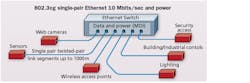
This Ethernet switch provides power and data through the MDI. The 802.3cg topology supports 10 Mbits/sec up to 1000 meters over a single pair to a variety of endpoints.
Running in parallel, to support the IEEE single pair standards, the TIA TR-42 Engineering Committee is developing single pair telecommunications cabling infrastructure standards.
This article is an overview of the single pair standardization by the IEEE 802.3 Ethernet Working Group and by the TIA TR-42 Engineering Committee.
Definitions: The IEEE 802.3 definitions of link segment, medium dependent interface (MDI), and physical layer entity (PHY) are used throughout the article and are described below.
- The Physical Layer entity (PHY) is the portion of the Physical Layer between the Medium Dependent Interface (MDI) and Physical Medium Dependent (PMD) sublayers. The PHY contains the functions that transmit, receive, and manage the encoded signals that are impressed on and recovered from the physical medium.
- The Medium Dependent Interface (MDI) is the mechanical and electrical interface between the transmission medium and the PHY and also between the transmission medium and any associated Powered Device (PD) or Endpoint Power Sourcing Equipment (PSE).
- The Link segment is the point-to-point full-duplex medium connection between two and only two Medium Dependent Interfaces (MDIs).
In Figure 1 (left) the Ethernet switch provides power and data through the MDI; in this case the eight-position modular jack (RJ45). The twisted-pair link segment is the medium (connectors and cables) between the MDIs. The example given is an 802.3cg topology supporting 10 Mbits/sec up to 1000 meters over a single pair to a variety of end points.
IEEE Std 802.3bw-2015 100BASE-T1
100Base-T1 is a single pair Ethernet standard designed to support 100 Mbits/sec operation in automotive environments (e.g. electromagnetic compatibility, temperature) over a single balanced twisted pair. The cabling system for 100Base-T1 consists of up to 15 meters of single balanced twisted-pair cabling, with up to four in-line connectors and two mating connectors with impedance in the range of 90 Ω to 110 Ω (nominal 100 Ω) to support a data rate of 100 Mbits/sec in each directionsimultaneously.
The length of cables in the automotive wiring system example (illustrated) can exceed 3 km with up to 1,500 cables and up to 3,000 contacts. The weight is up to 50 kg (~110 pounds). Unshielded twisted-pair for 100 Mbit/sec operation is preferred due to cost, weight and compactness.
The length of cables in an automotive wiring system can exceed 3 kilometers, with up to 1500 cables, as many as 3000 contacts, and a weight of up to 50 kg (approx. 110 pounds).

100Base-T1 link segment: The 100Base-T1 link segment specifications are the minimum cabling requirements specified to support 100Base-T1 operation. The cabling transmission parameters of the link segment include characteristic impedance, insertion loss, return loss, and delay. For single pair operation, noise coupled between link segments is considered alien crosstalk and therefore specified as power sum alien near-end crosstalk (PSANEXT) and power sum alien attenuation to crosstalk ratio far-end crosstalk (PSAACRF). Given that unshielded cabling is allowed, mode conversion loss is specified to minimize external electromagnetic interference and alien crosstalk noise coupled between link segments. The frequencies of the specified parameters range from 1 MHz to 200 MHz.
The link segment illustrated applies to 100Base-T1 (802.3bw), 1000Base-T1 type A (802.3bp), 802.3ch, and 10Base-T1S (802.3cg) for the automotive link segment.
IEEE Std 802.3bp-2016 1000Base-T1 PHY
1000Base-T1 is designed to support 1-Gbit/sec operation in automotive and industrial environments (e.g. electromagnetic compatibility, temperature). 1000Base-T1 is designed to operate over a single twisted-pair copper cable supporting an effective data rate of 1 Gbit/sec in each direction simultaneously.
Two link segments are specified.
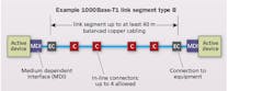
A) A link segment optimized for use in automotive applications that supports up to four in-line connectors using a single twisted-pair copper cable for up to at least 15 meters. This link segment is referred to as link segment type A.

1000Base-T1 type A link segment: The 1000Base-T1 link segment parameters are the minimum cabling requirements specified to support 1000Base-T1 operation. The cabling transmission parameters of the link segment include characteristic impedance, insertion loss, return loss, and delay. For single pair operation, noise coupled between link segments is considered alien crosstalk and therefore specified as power sum alien near-end crosstalk (PSANEXT) and power sum alien attenuation to crosstalk ratio far-end crosstalk (PSAACRF). Given that unshielded cabling is allowed, mode conversion loss is specified to minimize external electromagnetic interference and alien crosstalk noise coupled between link segments. The frequencies of the specified parameters range from 1 MHz to 600 MHz.

The link segment depicted here applies to 100Base-T1 (802.3bw), 1000Base-T1 type A (802.3bp), 802.3ch, and 10Base-T1S (802.3cg).
B) An optional link segment supporting up to four in-line connectors using a single twisted-pair copper cable for up to at least 40 m to support applications requiring additional physical reach, such as industrial and automation controls and transportation (aircraft, railway, bus and heavy trucks). This link segment is referred to as link segment type B.
1000BASE-T1 type B link segment: The 1000Base-T1 link segment parameters are the minimum cabling requirements specified to support 1000Base-T1 operation. The cabling transmission parameters of the link segment include characteristic impedance, insertion loss, return loss, and delay. For single pair operation, noise coupled between link segments is considered alien crosstalk and therefore specified as power sum alien near-end crosstalk (PSANEXT) and power sum alien attenuation to crosstalk ratio far-end crosstalk (PSAACRF). As unshielded cabling is allowed, mode conversion loss is specified to minimize external electromagnetic interference and alien crosstalk noise coupled between link segments. The frequencies of the specified parameters range from 1 MHz to 600 MHz.
IEEE 802.3 draft standard: IEEE P802.3ch Multi-Gig Automotive Ethernet PHY Task Force
This optional link segment supports up to four in-line connectors using a single twisted-pair copper cable for up to at least 40 meters. It supports applications that require additional physical reach.
The objectives of the P802.3ch related to the single pair link segment characteristics (cabling) and associated data rates are given below. Note that a draft standard is subject to change prior to publication.
The 802.3ch specification is to:
- Define the performance characteristics of an automotive link segment and an electrical PHY to support 2.5-Gbit/sec point-to-point operation over this link segment supporting up to four in-line connectors for at least 15 meters on at least one type of automotive cabling (e.g., UTP, STQ, STP, SPP, Coax, or Twinax);
- Define the performance characteristics of an automotive link segment and an electrical PHY to support 5-Gbit/sec point-to-point operation over this link segment supporting up to four in-line connectors for at least 15 meters on at least one type of automotive cabling.
- Define the performance characteristics of an automotive link segment and an electrical PHY to support 10-Gbit/sec point-to-point operation over this link segment supporting up to four in-line connectors for at least 15 meters on at least one type of automotive cabling.
The IEEE P802.3ch Link Segment is in development by the Task Group.
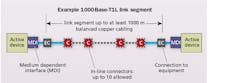
In a 10Base-T1L link segment, a single twisted pair supports up to 10 inline connectors, using balanced cabling, for up to at least a 1-kilometer reach.
IEEE 802.3 draft standard: IEEE P802.3cg 10-Mbit/s Single Twisted Pair Ethernet Task Force
The objectives of the P802.3cg related to the single pair link segment characteristics (cabling), associated data rates, and optional power techniques are given below. Note that a draft standard is subject to change prior to publication.

In the point-to-point powering topology illustrated here, single-pair Ethernet powered devices like sensors and actuators are connected to single-pair point-to-point link sections.
Two link segments are specified.
A) 10Base-T1S link segment for the automotive environment with single twisted pair supporting up to four in-line connectors using balanced cabling for up to at least 15 m reach.
10Base-T1S link segment: The 10Base-T1S link segment parameters are the minimum cabling requirements specified to support 10Base-T1S operation. As of December 2017, the cabling transmission parameters of the link segment include insertion loss, return loss, and mode conversion. Given that unshielded cabling is allowed, mode conversion loss is specified to minimize external electromagnetic interference and alien crosstalk noise coupled between link segments. The frequencies of the specified parameters range from 300 kHz to 200 MHz.
B) 10Base-T1L link segment for the industrial environments with single twisted pair supporting up to 10 in-line connectors using balanced cabling for up to at least 1 km reach. The 10Base-T1L link segment topology is illustrated on page 9.
10Base-T1L link segment: The 1000Base-T1L link segment specifications are the minimum cabling requirements specified to support 100Base-T1L operation. As of December 2017, the cabling transmission parameters of the link segment include insertion loss and return loss. For single pair operation, noise coupled between link segments is considered alien crosstalk and therefore specified as power sum alien near-end crosstalk (PSANEXT) and power sum alien far-end crosstalk (PSAFEXT). The frequencies of the specified parameters range from 100 kHz to 20 MHz.
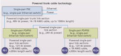
A “powered trunk cable” topology, illustrated here, currently is under study within the IEEE 802.3cg Task Group.
Optional power distribution: The 802.3cg objective to specify one or more optional power distribution techniques for use over the 10-Mbit/sec single balanced twisted-pair link segments is addressed in Annex 200A of the draft standard. The Annex defines the functional and electrical characteristics of the PD and PSE in the automotive and industrial environment.
Two powering topologies are recognized in the Annex “point-to-point” and “powered trunk” cable.
Power over Data Lines specifies a power distribution technique for use over a single twisted-pair link segment. It allows for power operation even if the data is not present and supports voltage and current levels for the automotive, transportation, and industrial control industries.
The point-to-point powering topology is illustrated atop the opposite page; single pair Ethernet powered devices, e.g., sensors and actuators connected to single-pair point-to-point link sections.
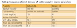
The classification of the power delivered to the PDs are given in Table 2. The minimum continuous power that the PSE shall be capable of supplying (Ppd) for the 1000-meter point-to-point link segment is given for each class. The 59-ohm loop resistance is derived from 1000 meters of 18-AWG stranded conductor cable and the 10 in-line connectors and the 39-ohm loop resistance is derived from 1000 meters of 14-AWG stranded conductor cable and 10 in-line connectors.
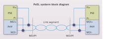
IEEE Std 802.3bu-2016 1-Pair Power over Data Lines (PoDL)
PoDL specifies a power distribution technique for use over a single twisted pair link segment and allows for power operation even if the data is not present. It supports voltage and current levels for the automotive, transportation, and industrial control industries. The PoDL system block diagram is illutrated. PDs and PSE systems are defined as compatible at their respective Power Interfaces (PIs).
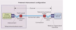
In this Power over Data Lines example, power sourcing equipment in the telecommunications room is interconnected to the horizontal cabling patch panel using an equipment cable. It enables power sourcing equipment (PSE) cabling reconfigurations at the patch panel using equipment cords.
PoDL power supply equipment (PSE) and powered devices (PD) are categorized by their classes. These classes and the relevant electrical specifications are given in Table 2. The power delivered to the PD is Ppd in watts.
As an example PoDL use case, an interconnection configuration is illustrated (“Powered interconnect configuration”) where PSE in the telecommunication room is interconnected to the horizontal cabling patch panel utilizing an equipment cable. The interconnection enables PSE cabling reconfigurations at the patch panel using equipment cords. In both configurations the powered device (PD) on the remote end of the horizontal cabling is connected to a telecommunications outlet via a work area cable.
In summary, we are in a brave new world of converged data and power. The single pair Ethernet and TR-42 standards (see sidebar) are poised to enable a new class of low-power Ethernet devices that will facilitate networking and powering the billions of end point sensors forecasted by the year 2022.
Chris DiMinico is principal of MC Communications.
ANSI/TIA standards
ANSI/TIA-568-C.0 provides information in Annex F for the environmental classifications that are used in this article and are described below.
MICE is an environmental classifications for the purpose of describing areas in which cabling is placed. The specifications of MICE include: M - mechanical; I - ingress; C - climatic; and, E - electromagnetic. MICE 1 (M1I1C1E1) generally relates to environmentally controlled areas such as commercial building offices, MICE 2 (M2I2C2E2) generally relates to a light industrial environment and MICE 3 (M3I3C3E3) generally relates to an industrial environment. The classification for areas with mixed environments may be described by including the classification level for each variable as a subscript (e.g., M1I2C3E1). If a cabling system component crosses an environmental boundary, the component or mitigation technique should be selected to be compatible with the worst case environment to which it is exposed.
TIA TR-42 single pair projects in TR-42.1:
• ANSI/TIA-862-B-2 intelligent buildings
Amendment to add single twisted-pair use cases, topology, and architecture to ANSI/TIA-862-B providing guidelines in buildings where 1-pair cabling can be deployed in addition to the 4-pair cabling used for IBS applications. The standard will include installation requirements and additional guidelines for transitioning from 4-pair to 1-pair cabling including sheath sharing. The standard will also provide single twisted-pair cabling guidelines for emerging IOT and M2M applications that will require higher density, reduced size, and greater flexibility to serve these IOT devices.
• ANSI/TIA-568.0-D-2 generic cabling
The scope of single pair TR42.1 generic cabling is under consideration in TR42.1. Presentations on the scope propose that TIA TR42.1 develop a standard to enable the migration of 100BASE-T1, 1000BASET-T1, 10BASE-T1 and 10GBASE-T1 into buildings by standardizing a generic single pair cabling architecture(s).
TIA TR-42 single pair project in TR-42.7:
• ANSI/TIA-568.5 - Single pair balanced twisted-pair telecommunications cabling and components standard
A single balanced twisted-pair cabling and components standard to provide specifications for cables, connectors, cords, links and channels using 1-pair connectivity in non-industrial premises telecommunications networks. The standard will focus on MICE1 environments and will include cabling and component performance requirements and test procedures, reliability requirements and test procedures, as well as guidelines for adaptations to four pair cabling.
The standard will include field tester specifications to verify the performance of installed single pair cabling. The cabling transmission performance requirements apply from 100 KHz up to 600 MHz.
100 meter and 15 meter channel configurations are supported. The 100 m test configuration is consistent with TIA-568 four pair cabling topologies. The 15 meter topology enables support for 100Base-T1, 1000Base-T1, 10Base-T1 and 10GBase-T1 technologies specified to operate over 15 meters of cabling.
• ANSI/TIA-1005-A - Single pair balanced twisted-pair telecommunications cabling and components standard
A single twisted-pair cabling and components standard to provide specifications for cables, connectors, cords, links and channels using 1-pair connectivity in industrial premises telecommunications networks. The standard will focus on MICE2 and MICE3 environments and will include cabling and component performance requirements and test procedures, reliability requirements and test procedures, as well as guidelines for adaptations to four pair cabling.
As the details in this article illustrate, we are in a brave new world of converged data and power. The single pair Ethernet and TR42 standards are poised to enable a new class of low power Ethernet devices that will facilitate networking and powering the billions of end point sensors forecasted by the year 2022.

