Standards bodies evaluate new test method
Coupling attenuation measures the electromagnetic isolation between a disturbing source and a channel.
Michiel Pelt
Alcatel Cabling Systems
Many cabling systems on the market today exhibit excellent performance well exceeding the limits specified in international and national cabling standards. This situation makes it very difficult for an end-user to choose between two cabling systems with the same attenuation-to-crosstalk ratio.
If today`s cabling systems are to support future applications, very complex encoding techniques will have to be used to achieve higher data rates over bandwidth-limited channels.
Data-transfer rates depend not only on channel bandwidth but also on the signal-to-noise ratio (snr). Error-free, high-data-transfer rates require a high snr, which can be achieved by decreasing the noise level (see "Bit transfer and Shannon`s Law," page 40).
Noise is caused by crosstalk and reflections inside the channel and by electromagnetic interference (emi) originating outside the channel. Some noise sources inside the channel are canceled out by modern network interface cards (nics), making higher bit rates possible. But, if ambient noise--or noise originating in the environment surrounding the cable--exceeds the level of internal noise, it may decrease the maximum achievable data rate over the channel.
The amount of noise picked up by a channel depends on the channel`s electromagnetic isolation. This parameter can be measured by a new test method called "coupling attenuation," which has been studied by the European Committee for Electrotechnical Standardization (cenelec--Brussels).
Noise sources
During transmission, various internal and external noise sources interfere with data signals. Inside a channel, noise arises from the adjacent wire pairs. Outside a channel, noise arises from equipment in the workplace, which decreases the snr and, consequently, decreases the maximum achievable data rate.
Most applications today carry information in opposite directions over two adjacent pairs. The noise inside a channel is caused by near-end crosstalk (next). However, emerging applications carry information over all four pairs in both directions simultaneously. Therefore, new kinds of noise sources appear inside a channel. Reflections cause noise if information is carried in both directions over a pair. Far-end crosstalk (fext) causes noise if information is propagated on two adjacent pairs in the same direction.
Inside a channel, next is the dominant source because the induced noise is stronger at the beginning of the channel, whereas the data signals are weaker due to the attenuation of the channel. Moreover, when all four pairs are used simultaneously, additional noise is induced on each pair. For this reason, nics for 1000Base-T are equipped with next cancelers to suppress this noise and, as the overall noise level decreases, higher data rates can be achieved. Likewise, noise caused by reflections and fext can be canceled out, decreasing the noise level even further.
In addition to the noise generated inside the channel, multiple sources that generate emi are present outside the channel. The channel picks up some of this electromagnetic energy from around the cable. Because external emi is totally unpredictable, it cannot be canceled out by nics. Its impact becomes more important when noise sources inside a channel are suppressed by cancellation techniques. When internal noise is eliminated, the workplace environment determines the noise level of the channel and its maximum data-transfer rate.
Noise suppression in channels
Segregating all the wire pairs inside a data cable or shutting off all the equipment inside a building would avoid possible sources of noise. An alternative approach is to reduce the coupling between existing noise sources and the data channel. In other words, increasing the electromagnetic isolation between the noise sources and a twisted pair results in higher data rates.
To reduce noise pickup, similar principles apply inside a channel as between a channel and its environment. Electromagnetic isolation is achieved by design, i.e., using components with good balance or screening. Implementing these physical effects has led to three different kinds of balanced cables on the market:
- unshielded twisted-pair (utp) cable, where noise reduction depends on balance
- screened twisted-pair (sctp) cable (also called foiled twisted-pair cable), in which an overall screen or foil together with balance reduces noise
- shielded twisted-pair (stp) cable, in which noise is reduced by the combined effect of balance and overall and individual-pair screening.
It is generally believed that stp has better electromagnetic compatibility (emc) performance than sctp. This misconception arises because all screened cables are considered the same, even though they are designed to achieve different internal or external electromagnetic isolation. In contrast to an sctp cable, the individual pairs of an stp cable are screened to achieve crosstalk improvement (next and fext), resulting in more bandwidth but also in greater isolation between a pair and its environment. sctp has emc performance equal to stp when the amount of overall screening of sctp equals the overall and individual-pair screening of stp.
next is a parameter that describes the emission and immunity properties of two adjacent pairs inside a channel. When measuring next between pair 1 and pair 2, or vice versa, similar results are obtained.
The same applies when characterizing the emc performance of passive devices such as cables, connectors, and cable assemblies. Both the immunity and the emission properties can be described by a single parameter equal to the ratio between the power of the field outside the channel and the power in the channel. This parameter, called coupling attenuation, expresses the electromagnetic isolation between a channel and its environment for any cable or channel construction.
Coupling attenuation for unshielded cable
For an unshielded cable or channel, coupling attenuation expresses the electromagnetic isolation provided by the balance. For a screened or shielded cable or channel, coupling attenuation expresses the electromagnetic isolation provided by the combined effect of balance and screening. It is a single design parameter that characterizes overall emc performance, enabling the user to compare an unshielded cable with extremely good balance and a badly balanced cable with a bad screen.
In a real-life situation, the power levels of the signals in the channel are much lower than those of the surrounding fields. Hence, more power is transferred from the environment to the channel than vice versa. Radiation from a channel can be ignored, whereas the susceptibility of a channel to ambient noise may cause an increase of the noise level if electromagnetic isolation is poor. Coupling attenuation tells an end-user how well a channel is protected against external noise sources.
The electromagnetic isolation of a channel can be measured in the same way as next: A signal is injected into one pair, which makes the channel radiate. The radiated power is not captured by an adjacent pair but by a current clamp surrounding the channel. This method has been studied by cenelec and written up in draft standard prEN 50289-6. Currently, it is also under discussion in the international and European standardization groups working on future cabling standards.
Experiments
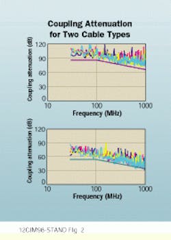
When symmetrical cables are tested for coupling attenuation, the recorded traces for each pair remain above an envelope curve. This curve is constant from 30 to 100 megahertz. Beyond 100 MHz, it decreases by 20 decibels per decade, meaning that between 100 and 1000 MHz, the coupling attenuation decreases by a factor of 100.
Coupling attenuation of a symmetrical cable is the sum of the electromagnetic isolation provided by the balance and screening, if any. Balance decreases with frequency by 20 dB per decade, whereas the screening effectiveness remains constant. Therefore, the traces for dual-foil cable are shifted upward with respect to the traces for unscreened cable. The difference equals the supplementary coupling attenuation provided by the screen.
In the same way, the next of an stp cable is about 40 dB higher than that of a utp cable over the entire frequency range. The coupling attenuation between the pairs increases because the pairs are separated by a foil around each pair.
Effect of environment
Data rate is affected by ambient emi when external noise exceeds internally induced noise. The maximum noise level that can be tolerated during normal operation is defined by application standards. These documents also specify values for next, fext, and impedance mismatches. If a channel does not satisfy these values, more noise arrives at the receiver ports, making it more difficult for the receiver to recognize the incoming data correctly. Consequently, the bit-error rate increases significantly. To avoid noise arising from next and reflections, 1000Base-T nics are equipped with special features. As a consequence, the maximum tolerated noise level inside a 1000Base-T channel is mainly determined by fext.
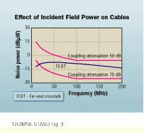
In the illustration, the noise power induced by fext for a signal of 0.5 volt traveling along the adjacent pair is compared with the noise power induced by an incident field of 3V per meter for a channel with different coupling attenuation. Active equipment must withstand such field strengths within residential, commercial, and light-industrial environments.
For a channel with a coupling attenuation of 50 dB, the noise induced by a field of 3 V/m is higher than that contributed by fext. Hence, the total amount of noise induced on the channel will increase and decrease the maximum error-free data transfer. For a channel with a coupling attenuation of 70 dB, the noise induced by a field of 3 V/m is negligible compared to that contributed by fext. Hence, the total amount of noise induced on the channel will not increase and the most error-free data transfer can be achieved. Therefore, the environment must be taken into account when designing data networks.
Michiel Pelt is a development engineer at Alcatel Cabling Systems (Brussels) and is a member of various standards committees within cenelec.
The coupling attenuation of a dual-foil cable (top) and an unscreened cable (bottom) is measured according to emerging European draft standard prEN50289-6.
The difference between noise power induced by fext and by a field of 3 V/m for two cables with different coupling attenuation is indicated.
Bit transfer and Shannon`s Law
To exchange data between equipment, bits must be transferred through a channel. The bits are encoded into a signal that should be recognized at the other end of the channel. The more bits encoded into a signal, the more complex the signal and the more difficult it becomes for it to be recognized correctly. Therefore, the maximum number of bits transferred per unit of time over a channel is limited by Shannon`s Law. According to this law, there exists a theoretical relation between the maximum error-free data rate over the channel, the bandwidth of the channel, and the signal-to-noise ratio (snr). For two channels with equal bandwidth, the maximum data rate depends on the difference in snr. If the snr equals 12 decibels, then four bits can be transferred error-free simultaneously, but if the snr equals 30 dB, then 10 bits can be transferred error-free simultaneously.
The ways to achieve higher data rates over a channel are limited. Increasing the bandwidth of the channel involves replacing the installed link with components that support a higher application class. But, for a bandwidth-limited channel, the only way to achieve higher data rates is by increasing the snr. Theoretically, these rates can be achieved either by increasing the signal level or by decreasing the noise level on the cable. However, the signal level is determined by the protocol of the application and by network interface cards. If you consider developments in the semiconductor industry, signal level will likely decrease in the future. Therefore, the only way to increase the snr of a bandwidth-limited channel is by decreasing the noise level.


