Commissioning a fiber-optic LAN
Reduce LAN restoration time by testing and adequately the system during installation.
John P. Breeden and Daniel E. Beougher
Tektronix Inc.
Commissioning a fiber-optic local area network (LAN) involves a series of steps that are taken to prove that the system meets the specified requirements. The requirements can be a series of specifications from the manufacturer of the system, the owner of the installation, or a third party such as a government agency.
The basic commissioning requirement of an optical network is that the optical fiber will pass enough light so that the system will operate. Often called "proof of performance" or "acceptance testing," the commissioning procedure usually covers specific parameters of the optical fiber and components, such as connector loss, splice loss, reflectance, and others. The list of parameters selected constitutes what are called the "as-built" measurements.
A lan may be as simple as two computers sharing a printer, or as complex as a campus network with hundreds of users. No matter how complex it appears, however, a fiber-optic LAN is basically a series of point-to-point connections. These connect-ions may be the links between workstations and routers, servers and backbone cable, or shorter links to printers and scanners. The network may be all-fiber, or it can be a composite of fiber-optic trunks with metallic branch cables. Its topology may be a ring, star, or bus.
Here we will look only at the fiber-optic portion of the LAN. Furthermore, we will look at each link as a single strand of glass. Also, we will assume that the fiber is multimode, since most lans today do not require the high bandwidth of singlemode systems.
With all these qualifications, the commissioning process might not sound simple, but it can be. However, the main task may be not the installation and testing of the system, as one might suppose, but documenting it and keeping the records in order.
Documentation is key
It is essential to look at network documentation, not just as a record of what you have installed, but also as a key to the future when the system crashes and recovery time is crucial. The average downtime of large lans in such a situation has been estimated to be 4 to 5 hours. With proper documentation and label- ing, however, you may save 70% to 90% in time to restoration, a significant savings not only of downtime but also of money.
Technicians frequently complain that most of the time they spend in restoration is wasted in searching for cable ends and various system components. Documentation during commissioning can dramatically reduce this problem.
Another factor that is often overlooked in commissioning a fiber-optic LAN is the user`s need for tools and test equipment. Users must recognize that the cost of lan ownership includes not just the initial purchase price of the system, but also the tools and trained personnel needed to keep it running. In some cases these maintenance costs can be substantially more than the installed system cost.
In addition to the appropriate splicing and connectorization tools, make sure you keep the proper test equipment on hand. One rule of thumb is that the cost of this test equipment should be approximately 20% of the total system cost. An optical time-domain reflectometer (otdr) and optical-loss test set (OLTS) are at the top of the list of test equipment if strict documentation procedures are to be followed. An OTDR, especially, can save hours of documentation time.
Components of lan documentation
There are three major components of proper LAN documentation: labeling, mapping, and archiving of test results. Without all three, lan maintenance and restoration will be tedious at best.
Labels are often taken for granted, but they are one of the most important items in a properly installed network. Fibers must be labeled as they are installed, to avoid the confusion that usually results if the task is performed after installation. Labeling may be done with a hand-printed wrap, machine-generated tags, or more exotic methods such as bar-coding.
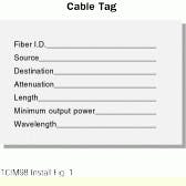
No matter how the labeling is done, however, the label must answer the following questions: What cable is this? Where is this end supposed to be connected? Where is the other end connected? What is the attenuation of the cable? How long is the cable? What is the minimum power output What is the wavelength? A cable tag in its simplest form will include answers to all of these questions.
A well-designed cable tag answers all relevant questions in a concise way. It includes a name or identifier for the fiber, so that the tag can be cross-referenced to detailed documentation and the fiber can be located on the cable map. The tag includes source and destination locations, so that the technician knows where each end is connected or terminated. Since loss and length are recorded, it takes only a few seconds to determine whether or not the fiber is broken or damaged to the extent that the loss has become unacceptable.
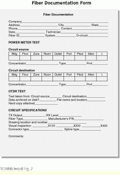
The information on the cable tag can be thought of as a snapshot. What other information is needed to give a more complete picture? The answer to this question depends on the requirements of the system owner. If we assume that a comprehensive and detailed record of each fiber we install is required, record-keeping will be much more extensive. The challenge in such a case is to make sure the documentation can be done quickly, accurately, and efficiently, while the result is a record that is solidly organized and contains all the fundamental information needed. Such a fiber documentation form can be thought of as a detailed extension of the cable label.
Getting good test results
Now that we have established a procedure for documenting our installation, let`s look more closely at the test equipment we need to measure the network parameters. The first requirement is a high-quality power meter capable of measuring the level or light exiting your transmitter or fiber. The power meter should be accompanied by a light source of the appropriate wavelength. Power meter and light source together are often referred to as an optical-loss test set.
Although technicians occasionally use the transmitter on the link as the light source, it is preferable to have a calibrated, handheld light source. otdrs with built-in light sources and power meters do not offer much advantage for commissioning tests because the testing is double-ended. Since you must have two units to complete the test, it makes more sense to have small, compact light sources and power meters that can easily be carried from location to location.
The most valuable piece of fiber-optic test equipment remains the OTDR, however. Today`s mini-OTDR, which is often used in lan applications, is capable of performing ex-tensive measurements and documenting the results, which tend to be both accurate and repeatable. The cost of the mini-otdr has dropped substantially below the current cost of mainframes and should be well within the test-equipment budget for lan installations.
With our instrument package now in place, it is time to test a fiber and fill in the blanks of the fiber documentation form. Such testing involves using both the olts and the OTDR.
Power-meter data is obtained initially. The first step is to calibrate the light source and power meter. Both units should be turned on and allowed to stabilize for a moment. Attach jumper cables to each unit and connect them by means of a barrel connector. Now you can "zero" the power meter, setting a reference level in the meter based on the light source being used.
Using the same jumper cables, attach the light source and power meter to opposite ends of the cable under test. It is preferable, if possible, to keep the jumper cables continuously attached to the olts while performing the testing to maintain the calibration of the devices.
You are now ready to test and record the attenuation of the fiber. The optical loss in passive components such as cables is measured in decibels (dB). Active components such as transmitters have outputs that are recorded in dBm, or decibels referenced to a milliwatt. Power-meter readings should be taken from both ends of the cable.
OTDR tests include five essential measurements: distance, fiber attenuation (dB/km), event loss, link loss, and reflectance. These five measurements provide useful information needed to document both multimode and singlemode lans.
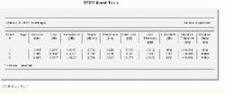
An OTDR typically provides a graphic display of the waveform, a look at the "inside" of the fiber, but it should also supply an event table. The event table logically organizes all the test data acquired during the test, converting the graphical elements of the waveform into numerical data.
Since the event table includes nearly all the data necessary to document the fiber, it makes an ideal vehicle for commissioning an installation. With one test you can display all events affecting the fiber, including the distances to different events, the loss across each event, and the amount of light reflected from mechanical events. The otdr allows you to identify losses in the fiber itself, severe bends in the fiber, and other factors that affect performance.
The information in the event table should be displayed in such a way that it can be easily archived and retrieved. Because so much information is found in a full event table, it would be onerous to copy it manually onto a fiber documentation form. Most otdrs and mini-OTDRs today are capable of storing test results and printing them out in hard-copy form, so that a printout can be attached to the fiber documentation form. This makes it easier to acquire and use comprehensive information, not only in installation but in later maintenance as well.
Among the parameters measured in a comprehensive event table are:
- Distance--is measured from the optical port of the otdr to an event. The degree of uncertainty for the measurement is recorded separately as distance tolerance.
- Event loss--refers to how much light is attenuated through an event. This loss measurement is made using measurement algorithms within the otdr. Events are acquired automatically by the otdr, marked and displayed on the waveform, and then listed on the event table.
- Reflectance--is the amount of light that is reflected by an event. Reflectance occurs at mechanical splices and connect-ors, but it is rarely found at fusion events. High reflectance can cause increased bit-error rates in lans. Collectively, reflectance is sometimes referred to as return loss.
- Fiber attenuation--is the average loss per unit of distance in the fiber in regions where there are no events. The unit of measurement is decibels per kilometer (dB/km).
- Dead zone--is a measurement of the rise of an otdr pulse, its pulsewidth, and the tail of the pulse. A short dead zone is an important feature of an otdr because it allows the user to resolve events that are close together.
- Link loss--is the net loss from the front panel of the otdr to an event. The measurement includes event loss and fiber loss.
- Loss tolerance--tells the user the mathematical confidence level he or she can attribute to the otdr when measuring the loss of a given event. There is an error factor in nearly all measurements made by any product; the otdr lists its own error factor to ensure the repeatability of measurements and the "believability" of results.
- Loss delta--is the amount of light lost between the event being measured and the previous event.
- Distance tolerance--is a similar measurement to loss tol- erance, except that it is measured on the horizontal, or distance, axis.
- Distance delta--is the distance between a measured event and the previous event.
Archiving and mapping the results
To have a useful lifespan, test results must be stored for future use. There are several ways to archive test results, with many technicians using them all:
- A hard copy can be printed out, sometimes using a printer built into the otdr or by connecting to an outboard printer. For efficiency`s sake, most technicians prefer to conduct a series of tests and then batch-print the results at the end of the workday.
- The results can be stored in the internal memory of the otdr and retrieved later.
- Test results can be stored using a floppy disk drive. The floppy disk can by the archival medium, or the information can be downloaded to another location.
- An external hard disk, such as that found in a personal computer or laptop, may have the capability of interfacing with a mini-otdr, allowing the technician to download test results. If this is the case, then external software is required to manipulate the documentation.
Following archiving, a map can be constructed to represent the network. Mapping can result in a simple wall chart or a detailed software database, or both. A chart usually takes one of two forms: a block diagram showing the trunks, branches, and general features of the network, or an architectural map detailing the paths to every workstation. Software is available that facilitates mapping the network, while also aiding in archiving. Cable management software can either be purchased off-the-shelf or custom-developed.
Is a map of the network really necessary? If the network is a small one, a map may not be needed, but most lans, whether optical or metallic (or both), are of sufficient size that a map is helpful to technicians who must be able to visualize the system in its entirety.
When all test results have been archived and the fiber documentation forms filled out, this information on the network infrastructure should be distributed to a minimum of three locations. One set of data should be archived, one set kept by the company`s manager of information systems or equivalent department head, and the final set should be kept on hand so that it is readily accessible for restoration operations.
Carrying out this commissioning procedure gives you the information needed to demonstrate that the lan will function, even before it is fully installed and operational. With specifications met and network parameters within tolerance, the installation will be successful, while maintenance and restoration operations will be much easier for the cable-plant manager to accomplish. In addition, there will be a permanent record of test results available for the future.
A simple cable tag should include the basic information needed to identify, locate, and characterize an optical fiber.
The fiber documentation form is a more detailed record of results from tests performed using an optical-loss test set and an otdr. The otdr trace and event table should be attached to this record.
The event table resulting from an otdr measurement is a detailed overview of the performance characteristics of every splice, termination, or other "event" found on an optical fiber.
John P. Breeden is product marketing manager for optical-cable test products, and Daniel E. Beougher is a consultant for Tektronix Inc. (Beaverton, OR).


