Air-blown fiber turns the wheels at AAM
ABF cabling provides advantages to installer and end-user alike in a heavy-industrial setting.
Gary Stepanian,
Clover Communications Inc.
A glowing red slab of steel moves into the giant press. The operator activates the press and, seconds later, a gear-shaped blank emerges, still red-hot and smoking. Two blocks away, in another building of this 18-city-block complex, robots insert red-hot axle shafts into induction hardening machines. Amid this intense, 24-hour-a-day, seven-day-a-week production routine, two installers are preparing to run optical-fiber data-communications cable to expand the plant`s local area network (LAN).
The new cable run will traverse three high-bay buildings with 60-foot ceilings, each filled with hot-metal processing machinery. The run will then span a road and travel through a parking garage. Like many industrial lan installations, this one has the potential to be costly, time-consuming, and hazardous. But right on schedule, the two installers finish pulling the tricky 1800-foot run of fiber cable--in less than 12 minutes and without breaking a sweat. How is this possible? With the FutureFlex Air Blown Fiber (abf) System from Sumitomo Electric Lightwave Corp. (Research Triangle Park, NC), a multibuilding lan expansion can be completed in a fraction of the time and at a fraction of the cost of conventional installations.
American Axle & Manufacturing (AAM)--with three plants and a technical center in Michigan, two plants in New York, and a dedicated axle facility in St. Catherine`s, ON, Canada--is a key first-tier automotive supplier. aam`s president and chief executive Richard E. Dauch, widely recognized as an innovative manufacturing strategist, reformed the company when he and two other investors purchased the existing business.
One of the new management team`s priorities was upgrading aam`s information management system. The contract was awarded to Electronic Data Systems, and a system was designed and installed by Clover Communications Inc. (Novi, MI), a national systems integrator. The goals of the cabling-plant upgrade and expansion were to improve product quality and reliability, accelerate time-to-market, and reduce product development costs.
The AAM Detroit Gear & Axle and Detroit Forge plants span 12 buildings covering 18 city blocks, with two city streets dividing buildings and a railroad spur isolating half of the structures. "We needed to find the right technology to allow us to upgrade all six of our locations, to make aam a world-class automotive supplier," says Bob Thomas, chief information officer at AAM. "Clover Communications brought to the table an innovative technology called the FutureFlex Air Blown Fiber System that could build the lan infrastructure throughout our plants with minimal production interference."
Clover`s project engineer, Bill Gasiorowski, registered communications distribution designer (RCDD), continues, "AAM was the first in the automotive industry to use the FutureFlex abf System. We showed them data from multiple installations in business, education, and government--and the evidence was compelling. Not only is there a significant reduction in installation time, but also costs are greatly reduced when the system is expanded or modified."
How ABF works
The FutureFlex ABF System uses compressed nitrogen to blow lightweight optical fiber through individual tube cells contained in flexible routing vehicles called tube cable. Tube cables can contain up to 19 cells and are constructed of materials suited to specific applications. Optical-fiber paths are defined by connecting tube cells with tube distribution units (TDUS) before blowing in the fiber. Fiber splicing is minimized or eliminated because a single continuous fiber can be blown through many tube cell segments, enhancing reliability and performance.
At AAM, the challenge was to adapt ABF`s proven campus-network technology to a particularly harsh plant-floor environment. Much of the installation required the installers to schedule work around hot-metal processes that run 24 hours a day, seven days a week. Once the cable was installed, production areas would not be readily accessible to make moves, adds, and changes.
The specific installation challenges at aam were as follows:
- required use of overhead cranes to access the machinery,
- difficulty in finding suitable terminal cabinet locations,
- high ceilings, many over 60 feet high,
- long distances back to data centers,
- high noise and heat environment,
- routing for many indoor/outdoor configurations needed.
The ABF tube cable system simplifies installations that span large areas, pass over trestles, run through beams, and are located underground. Once the tube cable is installed, additional fiber can be blown through without revisiting all of the hazards of the initial installation.
Clover had worked closely with Sumitomo Electric Lightwave, the U.S. manufacturer of the FutureFlex abf System, to develop installation standards that could be applied at many different kinds of job sites. Although earlier abf installations had been used as test beds to resolve the basic technical issues involved in blowing optical fiber, the aam project still presented new and specific challenges, including
- support for the ABF tube cable,
- development of new tube distribution units to support horizontal runs with drops to the hub cabinets,
- development of a redundant network needed because of the high uptime demands of the manufacturing world,
- devising a system where hubs could be cut in at a later time without disturbing adjacent active fiber,
- expansion and contraction testing over a wide range of temperatures,
- physical installation of 2000- to 3000-foot fiber runs in plants full of noisy, hot, and potentially dangerous machinery.
At AAM`s Detroit site, more than 30,000 feet of lightweight tube bundles were installed. An additional 50,000 feet will be installed. The longest splice-free fiber run is 2000 feet in length. Installations span both indoor and outdoor environments, with 90% of the installation routed inside buildings.
Collapsed backbone provides flexibility
A collapsed fiber-optic backbone design for each building was chosen to provide flexibility in the event of a failure or system modification. The multiplant sites will be using Asynchronous Transfer Mode building distribution switches. However, the conventional design reduces the fiber count of the home runs, severely limiting the logical architecture of the network design.
One of ABF`s big advantages is the capability to support multiple topologies designed into the network. For instance, while a distributed star backbone is the primary specified design at AAM, collapsed and ring topologies could be maintained simultaneously. This is due to the unique capability of the tube cables to be spliced into different configurations at each diverging point. Practical uses for this feature are found in fire-alarm systems, Fiber Distributed Data Interface rings, and in intrabuilding video and communications links.
The AAM design features a redundant and diverse routing scheme that feeds fiber from both directions in a given building loop. In case of a cut anywhere in the fiber run, then, only one-half of the feeds to each hub would be affected, since the feed going in the opposite direction is located in a different route.
The long runs permitted by using ABF technology--6000 feet or more--were ideal at aam because buildings were often 1500 feet away from the data centers and might include an additional 2000 feet of cable run front to back inside each building. Fiber-optic cables had to be able to run from the data center across a street, through several buildings, covering both indoor and outdoor spans, and then proceed to the individual plant-floor terminal cabinets. These cable runs sometimes had to go the long way around to provide diverse routing, and they had to accomplish all this without a single splice.
No other cabling technology offers this ability to mix environments in this way without needing splice points or transitional patch panels. The elimination of splice-point failures maximizes the reliability of the fiber`s light path, and the fiber run can be easily maintained because the only connectors are at the two ends.
After extensive study of the thermal expansion and contraction behavior of its abf products, Sumitomo Electric Lightwave concluded that the natural sweep resulting from appropriate field dressing at each tdu met existing expansion and contraction specifications. In addition, Clover improved the design of the plant-floor tdus to allow moving the tube bundles at termination points without compromising the National Electrical Manufacturing Association`s ratings of enclosures.
TDUS key to LAN flexibility
Clover developed a slotted TDU that permits adding tdus anywhere along the cable run without cutting other tubes that might house online fibers. A slotted box slides over the tube bundle, and the outer jacket of the bundle is opened only at the point where the appropriate tube is to branch off, preserving the integrity of adjacent online tubes and fibers.
Even though the original design for AAM located tdus at all conceivable locations, it was reassuring to know that additional units could easily be added in the future. This kind of upward flexibility is akin to future-proofing a lan against the unforeseen but inevitable changes that lie ahead.
One of the major advantages of abf is the capability to install small sections--1000 to 1250 feet in length--individually. Since tubes are easily connected and can be changed later, tdus or splice enclosures can be designed into the system at regular intervals. This permits cable runs to be installed in phases and with much smaller crews. Because the fiber is installed as a continuous run spanning many spliced-tube sections, the spliced-tube technique does not affect system performance or reliability.
tdu locations are generally chosen to permit splicing at divergence points, building exit points, manholes, or locations that cannot be installed until later. If a tube bundle gets cut, fiber can be blown out, tubes spliced, and new fiber blown in--usually in far less time than traditional fiber-splicing techniques permit.
Schedule flexibility and work savings
By comparison, in conventional innerduct installations, pull boxes are typically required every 100 to 200 feet. abf requires no pull boxes, since fiber is blown into the duct rather than pulled through it. Labor-intensive activities are also eliminated. For example, conventional fiber pulled into innerduct requires an installer at nearly every 90o turn, and often at vertical and horizontal turns as well. Spools must often be set up in the middle of runs, requiring figure eights of fiber to be laid on the ground. aam had no space to lay out fiber safely for such a procedure, nor could lifts be located where needed to pull fiber without disrupting plant operations.
At aam, abf tube cable was installed in phases that fitted the plant`s production schedule. Difficult locations were installed on weekends, and despite the potential for over- time costs, installation was so problem-free that overtime was minimal.
Instead of 10 to 15 installation crew members standing around while pulleys and figure-eight areas were set up, as would have been the case in a conventional fiber-optic installation, only one person at each end of a run was necessary to place abf from the data center all the way to the terminal cabinet. In addition, all splices, patches, and other potential causes of cable damage were eliminated.
The ABF cable design also eliminates the need for the slack boxes usually required in traditional fiber installations. This is because, when blowing abf, the slack can easily be wound inside of the terminal cabinet`s fiber patch panel. Should enclosures need to be relocated, fiber can be blown out, tube cable extended, and the fiber reinstalled.
ABF versus conventional fiber costs
All of these advantages add up to one thing: overall cost savings. Everyone is concerned about the cost difference between abf and conventional fiber systems. To calculate this savings, all cost issues must be included in the formula. For instance, people often want to compare the price per foot of conventional fiber-optic systems versus abf, which may be inappropriate. This is because there are many advantages to using abf, some of which are not easily quantified. Some of the factors that need to be considered are as follows:
- reduced production downtime during installation,
- reduced time and cost to repair abf, considering the cost of manufacturing run time is $1000 to $20,000 per minute,
- less need to overdesign, which is common in conventional systems--for example, putting in 96 strands of multimode and 36 strands of singlemode fiber, just to be safe,
- elimination of the cost of pull boxes, installation personnel, and damaged fiber due to the extra step of pulling conventional fiber,
- no penalty arising from the complications of pulling dissimilar lengths of fiber in the same innerducts,
- cash-flow savings created by deferring the cost of additional fibers until they are actually needed,
- savings that result from being able to wait until new technology is proved--for instance, gigabit fiber, which will likely be 50-micron and not 62.5-micron fiber that is in common use today, can be substituted at a future date,
- no need for additional electronics to compensate for signal loss caused by numerous splices typical of conventional fiber systems,
- reduction of waste caused when additional fibers are pulled through existing innerducts, which may result in new cables burning through existing ones.
It is clear, then, that ABF offers savings in many ways. And, since the manufacturing environment is both dynamic and unforgiving, abf offers advantages only dreamed of in installing traditional systems.
So, what are the cost savings enjoyed when using the FutureFlex abf System? Even without factoring in the qualitative advantages mentioned above, abf costs range anywhere from 20% less than conventional installations in those designs where significant overbuilding and patching are required to accommodate the conventional fiber, to 20% more for those designs that accommodate minimal growth.
Clover has performed numerous real-life cost comparisons, using designs optimized for differing technologies. The results show that the labor needed to install ABF is less than that for conventional fiber, while the material cost is greater than that of conventional fiber installation. However, taking into account the cost of electronics, patch points, overbuilding, testing, and additional items and procedures required by conventional systems brings the cost of abf into line with conventional fiber installations--so the dramatic flexibility of abf and the future-proofing it offers can be viewed as coming free.
Another key to the success of ABF has been the careful development of a skilled installer base. Proper training of installers and continued involvement on Sumitomo Electric Lightwave`s part with its proprietary technology is critical to high-quality installations. To satisfy the need for multiple sources of abf materials and services, Clover trains and licenses firms to become licensed installers.
The AAM project is just one of many examples proving how abf can be the lowest-cost and most practical choice for the data-communications networks of manufacturing companies thinking ahead to the next century. abf has proven to be a viable technology for addressing expansions, changes, and modifications to industrial-plant networks. The ease with which optical fiber can be added, rerouted, or removed from tube cells economically solves a host of vexing problems faced by network administrators in such environments.
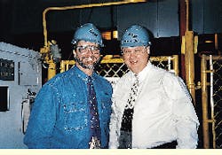
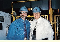
Bill Gasiorowski (left), project engineer with Clover Communica-tions Inc., poses with Bob Thomas, chief information officer at American Axle & Manufacturing, during the manufacturing facility`s recent data-network upgrade.
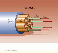
The tube cable used in abf installations is unlike conventional optical-fiber innerduct. Tube cable comes with factory-installed inner tubes, each of which will accommodate a single fiber bundle. Fiber bundles contain up to 18 optical fibers--either singlemode or multimode--and can be quickly blown into or out of inner tubes.
The FutureFlex Air Blown Fiber System manufactured by Sumitomo Electric Lightwave Corp. depends on tube distribution units such as this one to route tube cables through an installation.
Gary Stepanian, registered communications distribution designer (RCDD), is vice president of the Advanced Technology Group with Clover Communications Inc. (Novi, MI). Air-blown fiber is a technology manufactured under license in the United States by Sumitomo Electric Lightwave Corp. (Research Triangle Park, NC) and is called by the trade name FutureFlex. For ABF training and licensing, contact Bob Stratton at Clover Communications Inc. at (248) 471-0200.


