An optical-cabling infrastructure for data-center environments
Optical connections can meet the needs of high density and immediate availability.
Data-center design and cabling-infrastructure architecture have evolved over the years as needs and technologies have changed. In the past, the data-center manager relied on experience, as well as on what solutions previously worked and, more importantly, what did not work. Planning today’s data center, however, requires a more rigorous approach due to the faster pace at which the data center is changing.
In recent history, we used stacks of servers and large tape carousels; today, we see blade servers and RAID (redundant array of independent disks) systems. Your cabling infrastructure must be capable of servicing these ever-changing needs in the data center.
Fortunately, industry guidance has arrived, now that the new standard for data centers is available. The ANSI/TIA/EIA-942 Telecommunications Infrastructure Standard for Data Centers lists requirements and provides recommendations for data center design and construction. TIA-942 includes guidance relative to many areas, including grounding/bonding, pathways and spaces, and redundancy.
TIA-568-B, meanwhile, only addresses structured wiring. As the commercial building standard ANSI/TIA/EIA-568-B.1-2001 Commercial Building Telecommunications Cabling Standard has done for commercial LANs, the new data center standard provides a great tool for planning and designing the key components that make up a data center.
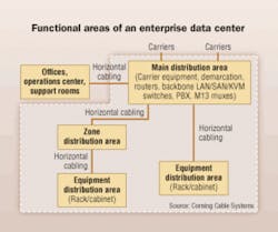
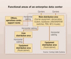
Using the TIA-942 standard as a guide, we see that the enterprise data center is divided into functional areas, including a main distribution area (MDA), zone distribution area(s) (ZDA), and equipment distribution area(s) (EDA).
The TIA-942 standard includes significantly more detail than will be described in this article; the standard is available for purchase from Global Engineering Documents (http://global.ihs.com/). Because most of the optical cabling within a data center is located within access flooring, we will focus on that section.
What solution to use?
The most efficient optical infrastructure is one in which all components are preterminated in the factory. All connectors are installed and tested in the factory and packaged such that components are not damaged during installation. The installer unpacks the components, pulls the preconnectorized cable assembly into place, snaps in all the connectors, and installs the patch cords connecting to the end equipment..and the system is up and running. This is the fastest installation method and provides the best solution for turning up servers quickly and with the least risk of not meeting the customer’s availability expectations.
Multimode remains the most common fiber type used in the data center due to the continued benefits of multimode electronics. Most data centers are using 50-micron (µm) multimode fiber in the optical infrastructure, along with a small amount of singlemode fiber.
The type of 50-µm fiber you use depends on the size of the data center and the applications currently running or planned for the future. If the design plan includes 10-Gbit/sec data rates, then one of the laser-optimized 50-µm fibers should be used. The most common fiber type used in data centers is 10-Gbit/sec 300-meter laser-optimized multimode fiber, which has a minimum effective modal bandwidth of 2,000 MHz•km at 850 nm, and provides bandwidth scalability from 10 Mbits/sec up to 10 Gbits/sec without needing to change the optical cabling infrastructure.
If a longer reach is needed, then 10-Gbit/sec 550-meter fiber is available that provides a minimum effective modal bandwidth of 4,700 MHz•km and allows 10-Gbit/sec operation up to 550 meters or 1,800 feet. This fiber is also backward-compatible down to 10 Mbits/sec.
Due to the continued high cost of singlemode electronics, singlemode fiber is used only for the special links that require its capabilities, including the OC (optical carrier) loop entrance into the data center and the core router connections. Also, IBM has standardized on singlemode fiber for its FICON server-to-director connections.
What cable to use?
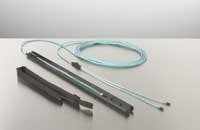
The best optical-cabling solution for the data center environment is preterminated cable assemblies and plug-and-play system preterminated connector modules. These assemblies, commonly referred to as optical trunks, consist of an optical cable with MTP/MPO connectors on each end. The MTP/MPO connector is a 12-fiber push-pull connector that operates much like the SC connector, only it connects 12 fibers at one time and is standard-compliant for Ethernet and Fibre Channel.
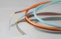
The type of cable to be used in the optical trunk depends on your data center environment and the fiber count. For low fiber counts, such as 12 or 24, the cable usually contains loose 250-µm or tight-buffered 900-µm optical fibers. For larger fiber counts, ribbon cables provide the best cable design because they offer higher fiber density and a resultant smaller cable diameter. Ribbon cables contain stacks of 12-fiber ribbons in a large, single tube. To give you an idea of how compact these cables are, a 96-fiber ribbon cable-48 channels of information-has an outside diameter of 0.54 inches.
Optical fiber provides the additional benefit of not suffering from the crosstalk problems that plague bundled copper cables. The smaller optical cables improve pathway utilization and minimize cooling-air obstruction when used in underfloor pathways. Use of overhead cable pathways does not present a cooling-air-impediment problem, but pathway fill is still important.
Regardless of the fiber count, distribution cables are used in the data center. “Distribution cable” refers to the cable’s ruggedness classification as specified in the indoor optical-fiber premises cabling standard ICEA S-83-596. This standard calls for a higher crush and tensile performance than the interconnect cable class that some cabling vendors use. The “interconnect cabling” classification refers to what is essentially patch-cord cable, and does not provide a robust-enough cable solution for use in overhead ladder rack or in basket tray under an access floor.
For applications where additional fiber protection is desired, interlocking armored cable is used since the spirally wrapped steel tape armor significantly increases the cable’s crush resistance. Use this cable design when multiple trades, such as electricians, plumbers, and others, will access the space under the access floor tiles. Damage to the optical cable due to accidental crush will be mitigated.
Regardless of the type of cable you use, it must meet certain flame ratings to be allowed in the data center. Since most access floor areas use the space below the floor as a cooling-air supply plenum, plenum-rated cables as specified in the National Electrical Code may be required for use in this space. Consult local building codes to verify compliance with the regulations in your area.
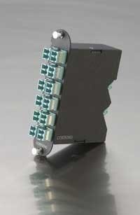
The connectorized ends of the optical trunk are shipped from the factory, installed in a covering that protects the connectors from damage during transit and cable installation. Preterminated plug-and-play system connector modules provide the interface between the MTP/MPO connectors on the trunks and the electronics ports. The module contains one or two MTP adapters at the back of the module, and simplex or duplex adapters on the front of the module. LC, SC, MT-RJ, or ST connector styles are still available on the front, and an optical assembly inside the module connects the front adapters to the MTP adapter(s) on the rear of the module.
The connector requested on the front side usually is determined by the connector style in the electronics, so that hybrid patch cords (which have different interfaces on each end, such as an LC on one end and an SC on the other) are not needed. The most common connector type in the data center is the LC, since it is now used on most new electronics.
When it comes to choosing a connector type, as stated before, the interface used in the electronics is what typically dictates. Usually, to keep things simple, you want the infrastructure connector type to match the electronics connector type. The LC is the most popular connector in the United States today.
Patch panel selection
Within the data center’s MDA, the fiber distribution frame (FDF) is established as the line of equipment racks or equipment cabinets that house the central termination point for all fiber connections. Fiber patch panels are located in the FDF and provide protection for the jumpers as well as strain-relief for the cables coming from the other data center areas.
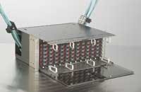
• A typical patch panel that can be used in the MDA is a 4U-tall housing (4U equals 4 × 1.75 inches, or 7 inches total height) that, in many cases, can efficiently house up to 288 fiber connections. The housing should have front and back doors to protect the connections contained within.
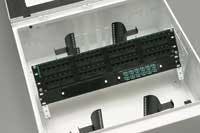
• The ZDA patch panel selection will depend on the available space. If space in an equipment rack or cabinet is available, then a 4U housing can be used. If no rack space is available, or if the data center manager prefers that this area be located under the access flooring, a fiber zone box can provide easy patch-cord access by housing up to 12 plug-and-play system connector modules in a pivoting bulkhead panel. With lower fiber counts, or where copper zone connections are needed in the same housing, this zone box can be reconfigured to allow fiber and copper connections in the same housing. A fiber zone box housing can also be used as your EDA administration point.
The preferred installation for the ZDA is above the access floor in a rack or cabinet, because administration is easier than it would be going under the floor when adding services or changing patch assignments. The ZDA is an interconnect point and provides connection between the MDA and the EDA; however, since space may not be available above the floor in a cabinet or rack, subfloor may be the only option.
• For patch panels in the EDA, since space is usually at a premium, you should use 1U housings. They provide fiber patch ports for up to 72 or 96 fibers, and let you add capacity incrementally (most users do not need full capacity from the start and so do not want to purchase the full 96-fiber capacity up front). Capacity is most frequently added in 12- and 24-fiber increments, and is accomplished by purchasing additional plug-and-play system modules. If the installed trunks did not account for future growth, then additional trunks will also be needed.
Minimizing disruption
Prewiring the data center with optical connectivity is the best way to provide bandwidth where it is needed. Optical trunks with 12- or 24-fiber plug-and-play system modules provide incremental bandwidth in an economical, easy-to-install package that minimizes disruption to the space and avoids having to remove a stack of floor tiles to pull a cable every time another server is added.
Using a zone architecture and providing space for future growth, along with selecting the appropriate optical fiber type, is the best way to ensure you will be able to satisfy your customers’ needs for a long-term, reliable, easy-to-scale infrastructure that installs quickly.
DAVID C. HALL is marketing manager with Corning Cable Systems (www.corning.com/cablesystems).
