Distributed power-data-video for closed-circuit TV applications
Convergence of security and IT means changes in cabling infrastructure.
Since the dawn of closed-circuit television (CCTV), RG-59 coaxial cable has been used to transmit video signals from the camera to the receiver end equipment. The system installer had to provide a nearby outlet and/or a power transformer. Additionally, most pan/tilt/zoom control functions required another twisted-pair cable.
This infrastructure is still the primary recipe for a CCTV system today. But an emerging solution that uses UTP cabling to transmit all video and control signals is available. Many argue it is a better solution than the traditional RG-59 approach.
Why change?
For the past 20 years, the telecommunications and data communications industries responded to market needs with extremely different cabling standards. Token Ring ran on 150-Ω shielded twisted-pair, IBM System 3270 ran on RG-62 coaxial, and Ethernet ran on RG-58 coaxial cable. Telephone signals were transmitted on quad wire or unrated UTP wire.
All of these separate cabling standards added up to one big headache for installers and end users. There was no common wiring, bulky coaxial cable seemed to exist everywhere, and there was no way to organize and manage all of it. As more and more systems were installed, the mess grew larger and more out of control.
The resolution of all this was the development of a common cabling system standard that would accommodate all applications in data communications and telecommunications. That standard has evolved to what is now known as the TIA/EIA-568-B set of specifications.
Open cabling system
Today, UTP-based CCTV solutions are available from a number of suppliers, and this type of video-transmission technology is now widely accepted along with coaxial and fiber cabling. In an effort to supply users with complete open-system cabling solutions, vendors, including Network Video Technologies, have developed product lines for handling data, video, and power transmission.
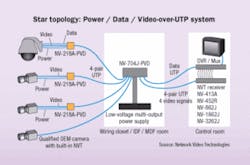
These product lines employ four-pair UTP cable and 8-pin modular (RJ-45) connectors. They let CCTV video, pan/tilt/zoom telemetry (data), and low-voltage power share the same 4-pair cable under one jacket. The low-voltage power uses two pairs of the UTP cable. This technology leverages the positive aspects of a structured cabling network architecture.
The RJ-45-style wiring pinouts are compatible with the data-communications and telecommunications industry standard TIA/EIA-568-B, so termination mistakes are minimized and testing can follow standardized procedures. Additionally, with the exception of 24-V AC, these signals may share the same wiring backbone as other signals, including data-communications and telecommunications.
Camera power
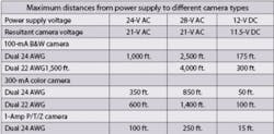
One advantage of using a structured cabling system and star-wired layout is that users can centrally locate power supplies. This is important because when employing a UTP-based technology, wire distance typically is limited due to voltage drop from the power supply to the camera.
Depending on the type of video-over-UTP system you use, it may not be compatible with standard Class 2 power supplies and voice-grade (Category 2 or better) wiring. If your system has this compatibility, you will not need to purchase exotic UTP cabling or proprietary power supplies.
Connecting to the control room
Generally speaking, in video-over-UTP systems power, video, and data are converted at the camera using a transceiver that employs a single four-pair cable with 8-pin connectors to deliver each camera’s signals to a concentrator-type device-called a cable integrator-in the wiring room. In systems equipped with such capability, the cable integrator receives low-voltage camera power from a third-party Class 2 power supply and delivers it to the camera cables. Control-room connections include four-pair, eight-pin modular connectors into a passive or active receiver hub. Cable integrators are available in several sizes, with varying numbers of connections available.
Leveraging the infrastructure
The advantages of a power/video/data-over-UTP system and your existing structured cabling system are numerous, including the potential for installation and use of off-the-shelf wire, power supplies, and connectors. Wiring may be installed and tested by subcontractors without the need for specialized skills or procedures. These conveniences reduce costs, not only in materials but also in cable deployment and termination labor. Existing voice or data cabling may be employed, allowing interbuilding connectivity without trenching. By contrast, coaxial cable is heavy, and difficult to handle and terminate-definitely not the CCTV medium choice of the future.
The video-over-UTP system also can eliminate problems associated with signal interference and surges. In many of these systems, active receivers are ground-loop immune and let the video signals be equalized for cable loss, thereby delivering a high-quality signal to the digital video recorder. Additionally, the structured wiring employed by a system like this leaves the door open for seamless migration to future-generation technologies.
Editorial Mission
Installers of premises and campuswide communications systems face constantly evolving standards, products, and technology. Keeping pace with these changes requires access to current inform-ation from informed peers who are knowledgeable in fiber and copper technology relative to premises communications. Cabling Installation & Maintenance provides peer-to-peer perspective in its interpretation of standards and technology, its presentation of installation techniques and in the selection and use of products in premises communications.
GUY APPLE is vice president of Network Video Technologies (www.nvt.com).


