Testing networks for Ethernet transmission
The need to transmit data on telecommunications networks is not new. In fact, the very first telecommunications systems could only transmit "data," in the form of Morse code. The networks that have since been built around the world, however, were designed to carry only one type of traffic-voice. The telephony network is the biggest machine in the world, with many millions of interconnections. Until recently, this network served its purpose well and it is only with the huge increase in the need for data transport-driven mostly by the Internet, that there has been any real need for change.
Data traffic has typically been carried on the telecommunications network by making it "look" like voice traffic, either by using a modem or, for higher-bandwidth connections, by packaging the data in such a way that it would fit into the standard 56/64-kbits/sec channel structure of the telecom network. But as the amount of data traffic in the network continues to grow, other means have to be found to carry the new traffic that are more bandwidth-efficient, less complex, and less costly.
There are several options for dealing with this increase in data traffic, and each approach has advantages and disadvantages. For example, one option is to build an entirely new data-only network. The biggest disadvantage of this approach, and for most of the other options, is the large amount of capital investment required. For this reason, most network operators are integrating data services into their existing networks, and they are doing so by using the next generation of Synchronous Optical Network/Synchronous Digital Hierarchy (SONET/SDH) network elements.
These new network elements carry all of the traditional T-carrier/PDH (Plesiochronous Digital Hierarchy) and SONET/SDH services, but also allow the transport of data services in their native format-Ethernet. This approach reduces network complexity for the customer and operator, leading to a lower overall cost and more efficient use of bandwidth.
Defining Ethernet
Ethernet is an asynchronous, frame-based protocol originally intended to provide a means of communication between more than two data devices, using shared media. Ethernet, fully defined by the IEEE 802.3 (2000) standard, has changed and evolved over time, increasing in speed and allowing the use of full-duplex transmission rather than shared media.
The current version of the standard allows for many variations of speed and media type, which are described by the following notation: [data rate in Mbits/sec][medium type][maximum segment length (100 meters)]. For example, the standard contains a specification for a10-Mbit/sec baseband system with a maximum segment length of 500 meters. The notation for this specification is 10Base-5. A media-type identifier often replaces the segment length; for example, the "T" identifier is used for systems running on unshielded twisted-pair cabling (the "T" is for twisted-pair).
All of the variations of Ethernet share the same basic frame structure, access control method (called media access control, or MAC) and, for systems using shared media, the same collision detection scheme (carrier sense multiple access/collision detection, or CSMA/CD).
Here are the most common Ethernet physical interfaces in use:
• 10Base-T: 10 Mbits/sec, baseband system, using Category 3, 4, or 5 twisted-pair cabling;
• 100Base-TX: 100 Mbits/sec, baseband system, using Category 5 twisted-pair cabling;
• 1000Base-SX: 1000 Mbits/sec, baseband system, using 850-nanometer (nm) multimode optical fiber;
• 1000Base-LX: 1000 Mbits/sec, baseband system, using 1300-nm singlemode or multimode fiber.
Ethernet frames
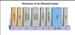
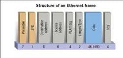
An Ethernet frame comprises up to eight different parts, only one of which (albeit the largest by far) is the data being transmitted.
The preamble and start of frame delimiter (SFD) are the first two parts. The preamble is alternate 1s and 0s; the SFD is always 11010101. These two parts allow for receiver synchronization and mark the start of the frame.
The destination address is six bytes in length. It includes the MAC address of the frame, usually written in a code language called hex, which is used to route frames between devices. Some MAC addresses are reversed, or have special functions. For example, FF:FF:FF:FF:FF:FF is a broadcast address that would go to all stations.
The source address is six bytes in length. It includes the MAC address of the sending station, also usually written in hex. The source address is usually built into a piece of equipment at manufacture. In most cases, the first three bytes identify the manufacturer, and the final three bytes are unique to the equipment. But there are some devices-test equipment, for example-in which the address is interchangeable.
The VLAN (virtual LAN) tag is four bytes in length and is optional. If present, it provides a means of separating data into virtual LANs, irrespective of MAC address. It also provides a priority tag, which can be used to implement quality-of-service functions.
The length/type field is two bytes in length. It is used to give either the length of the frame or the type of data being carried in the data field. If the length/type value is less than 05DC hex, then the value represents the length of the data field. If the value is greater than 0600 hex, then it represents the type of protocol in the data field. For example, 0800 hex means the frame is carrying Internet Protocol (IP); 809B hex means the frame is carrying AppleTalk.
The data is 46 to 1,500 bytes. This segment includes the client data to be transported, and would normally include some higher-layer protocol, such as IP or AppleTalk.
The frame check sequence (FCS) is four bytes. It is calculated over the whole frame by the transmitting device. The receiving device will recalculate the checksum and ensure it matches the one inserted by the transmitter. Most types of Ethernet equipment drop a frame with an incorrect or missing FCS.
The minimum legal frame size, including the FCS but excluding the preamble, is 64 bytes. Frames below the minimum size are known as "runts" and are discarded by most Ethernet equipment.
The maximum standard frame size is 1,522 bytes if VLAN tagging is being used, and 1,518 bytes if VLAN is not being used. It is possible to use frames larger than the maximum size, often called "jumbo frames," supported by some manufacturers' equipment in various sizes up to 65 kilobytes. Jumbo frames are identical in form to standard frames but with a bigger data field, which produces a better ratio of overhead bytes to data bytes, hence producing a more-efficient transmission. Jumbos are non-standard and manufacturer-specific and, therefore, interoperability cannot be guaranteed.
The frames are transmitted from left to right, least-significant bit first. The frames are separated by what is known as an inter-packet gap, which has a minimum length of12 bytes. The inter-packet gap exists because in a half-duplex system, time is needed for the medium to go quiet before the next frame starts transmission. The inter-packet gap is not really needed for full-duplex operation, but is still used for consistency.
Most Ethernet devices support autonegotiation. When two devices are first connected, they will send information to each other to declare their capabilities. The devices will then configure themselves to the highest common setting. The capabilities negotiated are speed, full- or half-duplex operation, and the use of flow control.
The OSI model
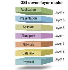
The OSI seven-layer network model presents a means of describing the functions of the various sections, or layers, of a data-communication system.
Ethernet covers the bottom two layers of this model: Layer 1, the physical medium (UTP, coaxial cable, optical fiber) over which the data is transferred; and Layer 2, the data link layer, which is the control mechanism for transmitting data onto the medium and receiving data from the medium.
Layer 3 is the network layer, the function of which is most commonly carried out by IP but could also be carried out by AppleTalk, IPX, or other such protocols.
The purpose of Ethernet is to ensure data is transferred over a link in a communications network, while the Layer 3 protocol has the job of ensuring the data is transferred over the whole network, from the original source to the ultimate destination. This transmission may use any number of separate Ethernet links.
The higher-layer protocols, Layers 4 and above, have the task of ensuring the integrity of transmitted data and presenting the data to the user or application. The function of these higher-layer protocols is of little interest in a transmission environment. A detailed description of the function of all seven layers of the model, and the advantages and disadvantages of the various protocols used in each layer, can be found in any good text on data networking.
Testing Ethernet services
The Ethernet connections mentioned above must be tested to ensure that they are operating correctly and that they are performing to the required levels. This assurance is accomplished by testing the bandwidth, delay, and loss of frames in the connection. In Ethernet terms, these characteristics are called throughput, latency, and frame loss.
Data throughput is simply the maximum amount of data that can be transported from source to destination. But the definition and measuring of throughput is complicated by the need to define an acceptable level of quality. For example, if 10% errored, or lost, frames were deemed to be acceptable, then the throughput would be measured at 10% error rate. It is generally accepted that throughput should be measured with zero errors or lost frames, and this article works under that assumption.
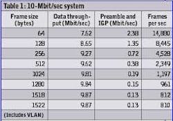
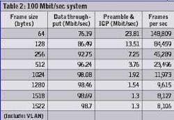
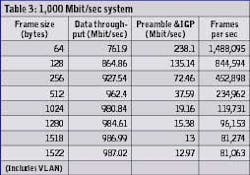
In any given Ethernet system, the absolute maximum throughput will be equal to the data rate; e.g., 10 Mbits/sec, 100 Mbits/sec, or 1000 Mbits/sec. In practice, these figures cannot be achieved because of the effect of frame size. The smaller frames have a lower effective throughput than the larger frames because of the addition of the preamble and the inter-packet gap bytes, which do not count as data. The maximum achievable throughput for various frame sizes is provided in the tables herein. (See tables, page 42.)
Latency is the total time taken for a frame to travel from source to destination. This total time is the sum of both the processing delays in the network elements and the propagation delay along the transmission medium.
To measure latency, a test frame containing a time stamp is transmitted through the network. The time stamp is then checked when the frame is received. For this to happen, the test frame needs to return to the original test set by means of a loopback (round-trip delay).
Frame loss is simply the number of frames that were transmitted successfully from the source, but were never received at the destination. It is usually referred to as "frame loss rate" and is expressed as a percentage of the total frames transmitted. For example, if 1,000 frames were transmitted but only 900 were received, the frame loss rate would be(1,000 - 900)/1,000 100% = 10%. Frames can be lost, or dropped, for a number of reasons-including errors, oversubscription, and excessive delay.
• Errors. Most Layer 2 devices will drop a frame with an incorrect FCS. This means that a single bit error in transmission will result in the entire frame being dropped. For this reason, bit error rate (BER), the most fundamental measure of a SONET/SDH service, has no meaning in Ethernet because the ratio of good to errored bits cannot be ascertained.
• Oversubscription. The most common reason for frame loss is oversubscription of available bandwidth. For example, if two 1000-Mbit/sec Ethernet devices are mapped into a single 622-Mbits/sec SONET/SDH pipe (which is a common scenario), then the bandwidth limit is quickly reached as the two Gigabit Ethernet services are loaded. When the limit is reached, frames may be dropped.
• Excessive delay. The nature of Ethernet networks means that it is possible for frames to be delayed for considerable periods of time. This is important when testing, as the tester is "waiting" for all of the transmitted frames to be received and counted. At some point, the tester has to decide that a transmitted frame will not be received, and count the frame as lost. The most common time period used to make this decision is two seconds. Thus, any frame received more than two seconds after it is transmitted would be counted as lost.
Service level agreements
In many cases, Ethernet services are being set up under what are called service level agreements (SLAs) between telecom carriers and customers. Often, quality of service (QoS) issues are raised, and this is one of the most discussed topics currently in the Ethernet services industry.
There are three main areas involved in determining what type of service to offer: bandwidth, delay, and loss of data:
• Bandwidth is a key factor, as more and more of it is required. Data transfer, e-mail, Web-based seminars and discussions, and Voice over IP (VoIP) are demanding more bandwidth from service providers. To support these services, an agreed bandwidth is usually set in the SLA, and proof is commonly required that the bandwidth will be available in the connection given by the service provider.
• Delay is another key factor in an SLA, especially when real-time services are being used. These services can range from Web-based seminars and presentations through VoIP. Long delay times in the network can cause these services to be disrupted or have a reduced quality. When VoIP is in place, long delay times can interfere heavily in normal telephone conversation, which is unacceptable to an end user. The other attribute about delay is that it should be constant. If the delay is fairly small but varies considerably during the transmission, problems will still occur in the use of real-time service.
• Loss of data is obviously unwanted in any network. A service provider will need to make sure that the Ethernet service being provided will not lose frames and packets when they are transmitted through the network.
Benchmark testing
How does a service provider perform tests that the customer will understand and accept? How long do the tests last, and what results mean anything?
The answer is Request for Comments 2544 (RFC 2544), which is a benchmark test that specifies certain criteria that allow both service provider and customer to meet an agreement. RFC 2544 requires the standard frame sizes (64, 128, 256, 512, 1024, 1280, and 1518 bytes) to be tested for a certain length of time, and a certain number of times. These testing characteristics are necessary because all these frame sizes are used in the network-so, the results for each must be known.
The characteristics tested in the procedure known as RFC 2544 are throughput, latency, frame loss, and back-to-back frames. Back-to-back frame testing involves sending a burst of frames with minimum inter-frame gaps to the device under test (DUT), and counting the number of frames forwarded by the DUT. If the count of transmitted frames is equal to the number of frames forwarded, the length of the burst is increased and the test is rerun.
If the number of forwarded frames is less than the number transmitted, the length of the burst is reduced and the test is rerun. The back-to-back value is the number of frames in the longest burst that the DUT will handle without losing any frames.
The RFC 2544 test asks for the results of all these tests to be recorded both in text and graphical formats. The results can then give accurate performance data for both service provider and customer.
The tests required under RFC 2544 can be performed manually, but they are tedious, time-consuming, and susceptible to errors. The easiest way to conduct this suite of tests is to have a fully automated test feature that lets the user simply enter details about the test scenario, then start the test. The test equipment then runs through all the requirements for the RFC 2544 test suite, and will display the results for the user.
NIGEL BURGESS is European business development manager for Agilent Technologies' FrameScope (framescope.com) and WireScope (wirescope.com)products.
