Taking cable testing into the digital age
Mark Mullins
Fluke Corp.
The move to digital technology provides some advantages over analog techniques, including great accuracy, high data volume, improved processing and manipulation of data and increased functionality. Not surprisingly, a digital approach to testing Category 5 cabling also yields a number of benefits, including faster testing times, higher accuracy and greater diagnostic capability.
The current generation of analog-based cable testers and network analyzers measures attenuation and near-end crosstalk by applying sinusoidal signals to the cables being tested and then measuring the response. To measure near-end crosstalk, for example, the tester applies a signal to one pair in the cable (say, the 1,2) and measures the response on another pair (say, the 3,6). The ratio of the measured signal to the applied signal is the near-end crosstalk.
According to the proposed TSB-67, the near-end crosstalk measurement must be made at hundreds of frequencies and between six different combinations of pairs in a 4-pair cable. Because some settling time is required between measurements, a single cable test can take quite some time. The result is a graphical display plotting measured crosstalk against the proposed TIA standard over a range from 1 to 100 megahertz. If measured crosstalk exceeds the standard at any point, the cable fails. This measurement method and the resulting plot are said to be in the frequency domain, because the measurements are made and plotted over varying frequencies.
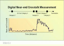
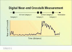
To measure the same critical parameter, a digital tester sends pulses that resemble 100-megabit-per-second local area network signals into one pair and captures the signal induced on another pair. The captured signal includes information on the magnitude and the location of the crosstalk. This measurement method and the resulting plot are said to be in the time domain, because the measurements are made and plotted over time (which is equivalent to distance).
How does a time-domain measurement compare to one made in the frequency domain? It can be mathematically proven that the time domain actually contains the frequency-domain information, but a technique known as Fourier transformation must be applied to extract it. It is possible to perform this conversion in a few milliseconds with a LAN cable tester that uses a digital signal processing chip. The resulting frequency-domain information is then compared against TSB-67 specifications, and a pass/fail result is delivered.
This use of digital technology provides a number of benefits to the contractor or end user. First, it addresses the technological challenges presented by TSB-67. Also, it delivers faster testing time, greater diagnostic capability and higher accuracy than analog technology.
The Telecommunications Industry Association/Electronic Industries Association-568A, as well as Technical Systems Bulletin-67, states that modular end connectors, commonly termed RJ-45s, are part of the equipment and not of the installed link under test. These modular connectors, whether connected to the installed cabling or the tester, make a significant, and yet variable and unpredictable, contribution to the near-end crosstalk performance of the link.
This fact raises an obvious question. How can a field cable tester accurately measure near-end crosstalk if the connectors with which you plug into the tester contribute in a significant way to the outcome? The answer is that accurate measurement cannot be accomplished without compensating for the connector, a task made even more difficult because there are two different link definitions in TSB-67.
Using the time-domain measurement method, a digital signal processor can compensate by analyzing the crosstalk contributed by the end connections. These effects are then subtracted from the near-end crosstalk measurement of the cable under test. The error added by the tester`s connector and the patch cable is reduced in this way from 1.8 decibels to less than 0.15 dB. Currently, only a time-domain approach can compensate for the connector and deliver standard compliance and high measurement accuracy for the basic link and channel configurations defined in TSB-67.
Basic link vs. channel
In TSB-67, the basic link, previously known as the contractor`s link, typically runs from a patch panel to a wallplate. When testing the basic link, the patch cord supplied with the tester can be used. The tester--particularly if it is an analog device--may have a special connector, such as a DB-15 or DB-25, in an attempt to introduce as little near-end crosstalk as possible into the measurement. This is a substitute for connector compensation.
On the other hand, a channel, sometimes known as the user`s link, includes the user`s patch cord as part of the link. This difference between the two links is key. Because the user`s patch cord must connect to the tester, the solution of using a DB-25 or DB-15 connector, with its special patch cord, is not acceptable. For the tester to link with the user`s patch cord in this case, an adapter would be needed, and such a device adds significant near-end crosstalk to the measurement.
The time-domain approach used by a digital tester, as noted, allows for connector compensation on both link types without special adapters.
Other benefits
Test time is another way in which digital technology benefits the user. A digital tester measures near-end crosstalk for the six combinations in a 4-pair unshielded twisted-pair cable from both ends of the link in less than 20 seconds--about two to seven times faster than analog instruments. At the same time, the device does not sacrifice data points to achieve testing speed. In fact, it analyzes near-end crosstalk performance at more points in the spectrum--every 100 kilohertz--than any other field tester on the market. This frequency interval is also more stringent than that required by TSB-67.
An important benefit of digital signal processing technology is that the cable tester can pinpoint the location along the cable where excessive crosstalk is occurring. Rather than telling the technician that a link fails because the worst-case near-end crosstalk value exceeds the limit at 85.6 MHz, for example, a digital tester reports that the major contribution to the crosstalk is occurring at 75 meters from the tester. The technician can identify this location and perform corrective action.
Of course, all the ease-of-use features in the world are worthless if the tester is inaccurate. Digital technology provides the highest accuracy available, so that a tester based on it can be expected to meet Level II accuracy requirements for both basic link and channel as specified in TSB-67, once it is ratified.
This conclusion is based on device tests utilizing mathematical modeling and comparison of actual test results to a network analyzer calibrated to standards set by the National Institute of Standards and Technology. The performance evaluation included all the parameters covered by TSB-67--noise floor, residual near-end crosstalk, output signal balance, common mode rejection, return loss and dynamic accuracy. Values for these parameters were run through a mathematical equation provided by TSB-67 to give a theoretical estimate of the instrument`s accuracy. For example, the TSB-67 equation yields an estimated near-end crosstalk value for the more accurate Level II tester of ?1.6 dB; using the same formula, the digital test device`s near-end crosstalk performance is better than ?1.0 dB.
Manufacturing consistency and tester repeatability have been verified by using units from different production lots to test the same link. The worst-case variation was found to be within ?0.4 dB.
A digital cable tester uses a time-domain technique that shows not only the magnitude but also the location of near-end crosstalk sources. In this case, a Category 3 link segment 65 feet from the cable tester creates a crosstalk problem.
Mark Mullins is marketing manager of the local area network business unit at Fluke Corp., Everett, WA.

