Tester accuracy an important concern for link performance certification
Testing Category 5 cable for near-end crosstalk has led to accuracy issues that TIA`s TSB-67 should resolve.
Mark Johnston and Jim Sciacero
Microtest Inc.
The issue of Category 5 testing has received much attention in the last year. Unfortunately, this attention has generated as much chaff and confusion as it has genuine information; the confusion comes from four sources--test equipment manufacturers, cable manufacturers, standards committees and the media. Most users believe they have been left to sort out the truth for themselves. To shed light on this confusion, we will look at how the whole accuracy issue evolved for Category 5 test equipment, at some questions you should consider when looking at test equipment and at what the new Technical Systems Bulletin 67 standard means.
Several years ago, field test equipment manufacturers began to compare the results they were measuring in the field against the pass/fail criteria available to them. In this way they could determine if a link was adequate. This approach generated two challenges--defining what constituted a pass, and dealing with borderline measurements near the limits of accuracy of the tester.
Until the publication of the Telecommunications Industry Association`s TSB-67, no official standard has been available for passing or failing the near-end crosstalk of links. Near-end crosstalk requirements for cabling by itself, and for connecting hardware, have been specified, but no one had yet agreed on how these elements combine to produce an overall near-end crosstalk requirement for a link.
In fact, the link itself was not clearly defined. Depending upon how many and what type of components were in the link, its near-end crosstalk characteristics would vary. In the absence of such information, field test equipment manufacturers have used the best available information to judge installed links, and that information comes from Electronic Industries Association/TIA-568.
The EIA/TIA-568 standard includes an informational annex, known as Annex E, that provides tables for the near-end crosstalk and attenuation of a worst-case link based upon a theoretical model. Users have discovered that the measured values acquired by field test equipment can be compared to the values in the Annex E tables. However, it has been argued that these tables should not be used because they are not a normative part of the standard. In other words, they are informative only. Field test equipment vendors have taken the approach that, given the absence of established values, using this table is the best method for evaluating links. Fast Ethernet and 100VG-AnyLAN designers have been using Annex E as a design guideline, too.
To solve the problems created by using Annex E of the EIA/TIA-568 standard to evaluate link performance, the TIA asked its link performance task group, EIA/TIA PN-3287, to prepare link performance transmission specifications for field testing unshielded twisted-pair cabling systems. The specifications are expected to be approved as TSB-67.
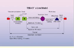
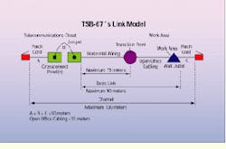
The new link model in TSB-67 defines specific requirements for near-end crosstalk, attenuation, length and wire mapping for the basic link and the channel. The basic link is what an installer might work with, and includes the wall plate, horizontal wiring and first crossconnection. The channel is what a user really needs to transmit information between a computer and a hub or concentrator. It can include two connections at each end. The near-end crosstalk and attenuation requirements are different for a channel and a basic link.
Fortunately, the channel requirements for near-end crosstalk in TSB-67 are identical to those published in Annex E, so links tested using EIA/TIA-568`s performance requirements will not need to be retested.
A second challenge has created confusion and controversy over Category 5 testing. Two examples illustrate this problem.
In one scenario, field test equipment is used to test 100 installed links. Four of these links fail near-end crosstalk by up to two decibels, and retermination or changing connectors cannot get them to a passing state. The end user refuses to pay. All the components are marked Category 5, so the installer rips out the cable and sends it back to the cable vendor. The cable vendor tests the cable with a network analyzer, and it meets Category 5 requirements. The cable vendor blames the field test equipment, saying it must have given an inaccurate result. The cable vendor then sends back new cable that is installed with new connectors; it passes with the same test equipment.
In a second scenario, the same four links fail, except that this time the connector vendor comes on-site with the network analyzer and says the links actually pass by up to 2 dB. "Don`t trust that cheap test equipment," the connector vendor says.
There are three different ways to explain the failures in these two scenarios. First, there has been no agreed-upon methodology for making network-analyzer measurements on links. Second, in both cases, the link characteristics were changed when the second measurements were made, so it is impossible for the readings to agree. And third, every measurement by every piece of test equipment (including network analyzers) has an inherent level of uncertainty.
Standard methods needed
The first problem concerns the fact that because there has been no standardized way to make near-end crosstalk measurements, different testers have given different results. Unless you specify a consistent methodology for how you approach a measurement, you can expect inconsistent results.
For example, if someone asks how far it is, in feet, from New York to Boston, you might assume the distance is measured from city limit to city limit, while someone else might assume it to be from city hall to city hall. You might assume measurement over surface routes and another might assume a straight-line measurement. Until you establish a consistent frame of reference, you can come close, but you cannot hope to exactly match the distance.
The second problem in comparing field test equipment results to those of the network analyzer is that the characteristics of the link often change before you have the opportunity to make a comparison measurement. Near-end crosstalk is extremely sensitive to any change in the link. Remove a patch cord, and the near-end crosstalk changes. Reterminate a connection, and the crosstalk changes. Bend a cable, and it changes again.
Previous common practice
Until recently, it was common practice to cut off the ends of cables so they could be connected into the network analyzer. Because the connector was now gone, it was impossible to get correlation between measurements. It is unrealistic to expect two separate measurements to agree when the link to be tested has changed between measurements.
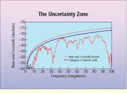
The third problem is that of measurement uncertainty. All measurements by any device have an associated uncertainty value. This can be thought of as an uncertainty zone that might apply when measuring near-end crosstalk on a cable. For example, the measured near-end crosstalk value of a cable may actually cross above the Category 5 limit in several places. But if the measurement accuracy of the instrument is plus or minus 2 dB, and your result is a fail by 0.3 dB, what can you conclude? If each of two instruments has an accuracy of plus or minus 2 dB, then any results they provide that are within 4 dB of each other cannot be said to be in disagreement.
In fact, in recent TIA round-robin link testing using network analyzers, while there was generally agreement, there were several cases where results disagreed by more than 2 dB; in other cases, the shape of the near-end crosstalk curve was very different from machine to machine. And this was in a controlled environment, with calibrated network analyzers operated carefully by experts.
An issue that compounds other problems is the fact that accuracy is a function of frequency and dynamic range, so that accuracy measured at one point on the curve will not necessarily be the same as the accuracy at any other point. Generally, at lower near-end crosstalk values and higher frequencies, you will see increased uncertainty. Some users have mistakenly evaluated field test equipment at one point "down in the muck," well below the intended operating range, and then have extrapolated the same uncertainty up at the Category 5 curve.
What causes results to be uncertain? This subject has received much scrutiny in the last year. Approximately one dozen performance parameters contribute to the accuracy--or inaccuracy--of near-end crosstalk measurements, although only two or three of them have a major impact.
Residual near-end crosstalk loss, one of the high-impact factors, results from the effects created by components within the tester. All test equipment, adapter cables and connectors unavoidably have a certain amount of inherent crosstalk. This internal crosstalk is not part of the channel to be tested. In a perfect instrument, the receiver would be completely quiet in the absence of external signals. However, all instruments generate some noise that will impact the accuracy of measurement.
Also, before signals reach the receiver, they pass through a mated connection, as well as a number of traces, relays and other components that can contribute additional near-end crosstalk. Because of its design limitations--for example, adjacent parallel conductors--the modular 8-pin connector, while convenient, is not ideal for minimizing near-end crosstalk. Field test equipment that uses modular 8-pin connectors will usually support what is known as accuracy Level 1 performance, but not accuracy Level 2, because the modular 8-pin connector`s TSB-40A performance rating is -40 dB at 100 MHz, while accuracy Level 2 requires -55 dB at 100 MHz.
Another performance parameter that affects near-end crosstalk accuracy is balance. Twisted-pair transmission systems typically use signal formats that define tip and ring signals that are equal in amplitude and opposite in phase. This is known as a balanced transmission scheme and is used to reduce radiation and coupling of signal to other conductors. In a balanced transmission scheme, the fields from the tip and ring conductors cancel, eliminating coupling.
Balance is a measure of how well the tip and ring signals are matched in amplitude and the desired reversed-phase relationship. In a perfectly balanced transmission environment, there is only a differential signal component on the pair. However, in an unbalanced condition there is a differential- and common-mode signal component. The ratio of common mode to differential defines the degree of balance.
In field test equipment with poor balance, unwanted common-mode signals are converted to differential crosstalk, creating signaling errors. Accuracy Level 1 instruments are required to have 27 dB of balance, while accuracy Level 2 units must have 37 dB.
Other areas of potential error include return loss, noise floor, common-mode rejection ratio and detector accuracy. The TSB includes an experimental model that combines the error terms into an equation that predicts the overall accuracy of the device. This model is a useful starting point, but as of the time of this writing, is only theoretical and has not yet been proven in the field. Ultimately, users faced with any discrepancy will likely compare field measurements against those of a network analyzer.
New TSB needed
TSB-67, when published, will be a good starting point for establishing a common baseline for field test equipment. Included are requirements for basic performance parameters, methods for establishing accuracy claims, channel and basic link performance requirements, test definitions and methodologies for network analyzer use. Users should expect that products that are TSB-67-compliant are running the same tests, using the same pass/fail requirements and reporting information in the same way. Differences will be evident in ease of use, portability, performance, speed, reliability, secondary functions and cost.
Therefore, in the absence of a standard, testers sometimes need to be tested when "close calls" need to be made. The problem is that there has been much variation in the way the measurements are made, leading to contradictory results. With the publication of TSB-67, things should change. Accuracy issues, test methodology and consistent pass/fail requirements will be clarified for everyone. If a field tester is TSB-67-compliant and can demonstrate good correlation with a network analyzer, you can use it with confidence.
The link model from TSB-67 defines a basic link and a channel.
Accuracy variation in field test equipment creates an uncertainty zone. Measured results for near-end crosstalk that are near the Category 5 channel limit, for example, may be difficult to interpret accurately.
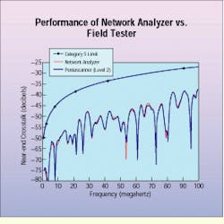
A plot of the correlation between a network analyzer and field test equipment that exceeds accuracy Level 2 requirements shows excellent agreement, even far below the Category 5 curve.
Mark Johnston is director of technology development at Microtest Inc. (Phoenix). He is a voting member of EIA/TIA`s TR-41.8.1, has contributed to ISO IS 11801 and is on the technical advisory board of the Certified Network Expert consortium. Jim Sciacero is engineering manager at Microtest. He is also an active member of EIA/TIA TR-41.8.1. and has made significant contributions to TSB-67.


