Termination Techniques Reflect Copper Cabling’s Versatility, Utility
Key Highlights
- Copper termination methods have evolved from punchdown IDC blocks like 66 and 110 to sophisticated patch panels and proprietary connectors, reflecting technological advancements.
- Tools such as impact punchdown tools and tool-less jacks have improved efficiency, but changes often require retermination, highlighting ongoing challenges in cabling flexibility.
- The introduction of MPTL systems addresses modern network architecture needs, enabling ceiling-mounted device connections and supporting high-performance standards like Category 6A.
- Innovations by vendors continue to enhance performance, with features like high-density patch cords and specialized plugs designed for field termination, ensuring reliable and scalable network infrastructure.
Depending on the year—or the decade—in which a communications cable installer entered the trade, the primary method that installer used to terminate a twisted-pair copper cable could vary significantly. And the longer an installer has been at their craft, the more copper-termination methods they likely have mastered. Whether an installer cut their teeth on the 66 block or a tool-less 8-pin modular connector, the types of terminations they conduct on a regular basis reflect the versatility and effectiveness of copper cabling in enterprise and other network environments. This article will take a look at the evolution of copper-termination technology, focusing on the products and tools involved.
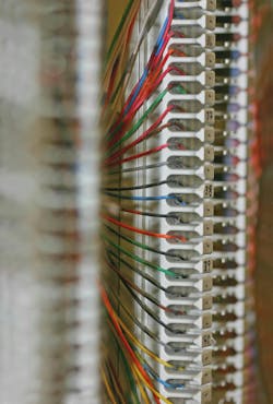
When telephony was the primary or only communication system within an organization, the 66 block was ubiquitous. It delivers an insulation displacement connection (IDC) termination, meaning that during termination, the insulation around the copper conductor is cut and the exposed conductor directly meets the block’s metal contact, forming a gas-tight connection.
Installers terminate each conductor to a 66 block individually in a process called the punchdown. The impact tool used on a connecting block, commonly called a punchdown tool, accommodates different blades. The blade used for a 66 block impacts a single wire, terminating the copper conductor to the block’s contact and cutting the excess wire. 66 blocks are vertical in orientation and typically are wall-mounted. Often the 66 block is used to accomplish a cross-connection, often between phones in work areas and a private branch exchange (PBX).
66 to 110
While the 66 block remained popular when data networking took hold, and supported data transmission of multiple megabits per second, the 110 block gained popularity thanks to its efficiency and performance. The 110 block is space-efficient in that it delivers more conductor terminations per square inch than a 66 block does. It can be mounted to a wall or within a rack, with space behind the block available for cable routing and management.
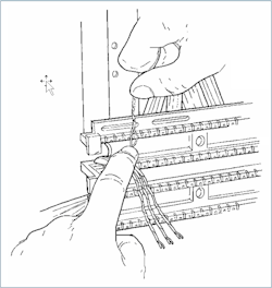
Installers lace wires side by side into the holding slots of a 110 wiring block base. They could then use a 110-specific blade in the impact tool to cut each wire to length. In general, for improved efficiency, the installer uses the multi-pair impact tool to cut all eight conductors of a 4-pair cable to length all at once in the side by side holding slots. After all cables on the wiring block are cut to length, the installer will punchgas-tightdown 4-pair connecting blocks on top of the wiring block. Each connecting block contains eight double-sided IDCs. This punchdown operation makes high contact force connections between the cable conductors and the bottom of the IDCs. These high contact force connections are also referred to as gas-tight IDC terminations To complete a low-speed voice connection, cross-connect wire can be punched down on the top of the IDC connecting blocks. Alternatively, 110 patch cords can be pushed onto the top of the IDC connecting blocks to complete a data connection, generally up to Cat-6 performance levels.
A major disadvantage of both 66 and 110 blocks is that changes to the cable terminations require the literal ripping out and retermination of wires. That said, IDC blocks are still being installedin many telecommunications rooms (TRs) today due to their space-saving wall-mount capability and proven durability and reliability. Vendors, such as CommScope have continued to add innovation to their IDC block solutions to improve performance to Cat-6A and add unique features. Luc Adriaenssens, VP of R&D at CommScope’s Enterprise unit stated “Our reverse-direction VisiPatch® patch cords hide the clutter of patch cords without needing horizontal wire managers thereby creating a clean high-density solution for large installations.” IDC block usage will thus likely continue, especially when wall-mounting is highly desirable.
The practicality of patching in racks
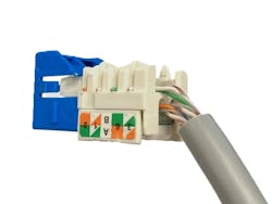
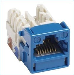
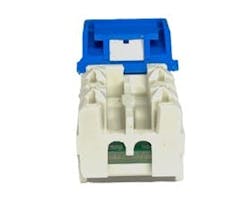
The patch panel answers this challenge and soared in popularity when premises data networks rose to prominence in the workplace, particularly in open-office cubicle-style workspaces. A patch panel contains a number of 8-position 8-contact (8P8C) modular jacks, often ganged into equivalent multi-jack modules. The mating interface in the front of the jack is standardized with stringent dimensional controls to ensure interoperability. The designs at the back of each jack, where the 4-pair copper cable is terminated is not dictated by standards, thus enabling unique implementations by vendors. The exact strip length and detailed routing of pairs at the point of termination is an important factor that can degrade performance substantially if not done precisely. Following each vendor’s detailed jack and panel termination instructions is paramount to assuring the inherent performance of the connectors is not compromised by their installation.
The permanent link is the fixed portion of a twisted-pair copper cabling system that is terminated to modular jacks on each end. One end of the permanent link typically is a jack (or multi-jack module) housed in a patch panel within the TR. These jacks, or ports, on a patch panel receive patch cords that then attach either to a piece of network equipment such as a switch (in the case of an interconnect) or to a port within another patch panel (in the case of a cross-connect). The other end is located at the work area, ready to receive a patch cord whose other end will plug into a network interface card (NIC) on a device such as a computer.
The processes, tools, and technologies behind the termination of copper cables to these jacks has evolved over the years, driven in part by the increasing speeds with which data is transmitted over copper cabling. Generically, the process involves lacing the wires through the jack and using a punchdown tool to create an IDC for each conductor. This process is similar for 8P8C jacks up to and including the Category 6 performance level.
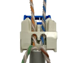
When Category 6A connecting hardware was developed to support 10-Gbit/sec transmission speeds, it became necessary to invent new designs within the jack to compensate for the crosstalk inherent in the 8P8C plug-to-jack connection and further refine the level of control at the point of cable termination. Some of these new designs included characteristics like different-than-conventional spacing of the IDC contacts at the back end of the jack, and substantial refinement of the compensation complexity and precision on the printed circuit board (PCB) inside the jack. Because these designs were proprietary to the companies that created them, installers who work with multiple manufacturers’ products had to learn unique termination techniques for each brand.

In the midst of this growing complexity, also came simplification. A number of manufacturers introduced jacks that claim tool-less termination, although these products could more accurately be described as “fewer-tool jacks” than truly “tool-less jacks.” In general terms, a tool-less jack contains a lever-like piece that closes onto the laced wires and terminates them to the contacts. Cables that are terminated to these jacks still require prep tools such as a jacket stripper and a snipper. Other innovations included adding razors to jack termination caps or within multi-pair termination tools which ensure conductor wires are easily cut at once at precisely controlled points.
Enter the MPTL
Another area of significant technological and workmanship evolution in the realm of copper cable termination occurred in the plug. Enterprise networking has evolved to a point at which a number of devices are located—and connections to these devices takes place—near the ceiling as opposed to near the floor. The proliferation of wireless LANs in enterprise networks was a primary driver of this evolution, with multiple wireless access points being placed at ceiling level to offer coverage across an area. The popularity of IP-based video surveillance systems also factored in, resulting in cameras being placed at ceiling level.
These network devices have 8P8C (RJ-45) ports built-in and accept one or more RJ-45 plugs. In years past, constructing a standard-compliant cabling channel required the use of a work-area cord that inserted into the access point, camera, or other device on one end and into a work-area outlet jack on the other end. Without the installation of a new outlet at ceiling level, that meant running a work-area cord from the ceiling-level device down a wall to an outlet located approximately 18 inches off the floor. Alternatively, a building occupant could have a work-area outlet installed closer to the ceiling and run a shorter cord from the outlet to the device. Neither option is ideal.
This cabling-architecture challenge gave rise to the modular plug terminated link (MPTL), a topology in which the end of a horizontal cable that serves the work area is terminated to a plug rather than a jack. The Telecommunications Industry Association (TIA) officially recognized the MPTL in 2018 with the publication of ANSI/TIA-568-2-D.
Inserting a field-terminated plug—as opposed to a patch cord’s factory-terminated plug—directly into network equipment presented both a challenge and an opportunity. Terminating copper wires to RJ-45 plugs has been uncommon and generally discouraged for higher-performing copper systems of Category 6 and higher. MPTLs that needed to deliver Category 6A performance posed a formidable challenge to installers. Likewise, manufacturers of twisted-pair copper connectivity faced a challenge they leveraged into an opportunity.
Through research-and-design efforts, a number of manufacturers developed plugs designed specifically for field termination and MPTL applications. These plugs, akin to Category 6A jacks, are unique and proprietary to the manufacturers that produce them. The methods and tools used to accomplish field termination vary, from being fairly similar to traditional termination methods, to being significantly dissimilar from traditional methods.
Terminating copper conductors has always been a fundamental activity for network installers, dating back to the days before data networking came to prominence. The evolution of twisted-pair copper termination methods reflects the practical use of copper systems in corporate and other enterprise networks. Manufacturers of connectivity hardware continue to refine their product offerings to make the process—and the resulting cabling circuits—higher performance and more efficient.

